How Charger Engineers Evaluate Alternative Components Before Replacing a Part
Provider of Information: Michael Chen (Engineer) & Luo Zhang(Production Supervisor)
Why Similar Specifications Do Not Always Mean Equivalent Performance
In charger manufacturing, a component shortage can create pressure to find a replacement quickly. A purchasing team may identify a part with a similar datasheet, a better price, or a shorter lead time. At first glance, the substitution may look straightforward.
For an engineer, however, the question is more specific: will the alternative component behave correctly in the actual charger circuit, under the intended operating conditions, and within the product's manufacturing and compliance requirements?
A power IC with a similar rating may use a different control method. A MOSFET with comparable voltage and current specifications may have different switching characteristics. A capacitor may match the nominal capacitance but differ in temperature behavior, lifetime, or physical dimensions.
These differences do not automatically make a replacement unsuitable. They mean the decision requires engineering evaluation rather than a simple comparison of headline specifications.
For USB-C PD chargers, GaN fast chargers, PPS products, and high-power multi-port chargers, alternative component evaluation is the engineering process used to determine whether a proposed replacement meets the requirements of the existing design and what verification is needed before the change is released.

Why Charger Components Cannot Always Be Replaced Directly
A charger is a system in which components interact. The suitability of an alternative depends not only on its individual specifications but also on its position in the circuit, surrounding components, operating conditions, and product requirements.
Four factors are particularly important.
1. Electrical characteristics
Voltage, current, power, resistance, capacitance, and other headline ratings are useful starting points. They do not necessarily describe all the characteristics that matter in the actual circuit.
Depending on the component, engineers may also need to consider switching behavior, transient response, leakage, parasitic characteristics, control thresholds, or protection behavior.
2. Thermal behavior
Components generate and transfer heat differently. Changes in losses, package construction, thermal resistance, or mounting conditions may affect the temperature of the component and surrounding areas.
This is relevant in compact chargers, where available space and thermal paths are limited.
3. Mechanical and manufacturing compatibility
A replacement may have a different package, pin arrangement, footprint, height, or assembly requirement. Even when the electrical function appears equivalent, these differences can require PCB changes or manufacturing adjustments.
4. System-level interactions
A charger must meet its overall electrical and functional requirements. Replacing one part can influence the behavior of other parts of the circuit, so the engineer needs to evaluate the replacement in context.
The correct question is not simply whether two components look similar on paper. It is whether the proposed alternative is suitable for the design in which it will be used.
Step 1 — Define Why the Replacement Is Needed
Before comparing components, the engineering team should understand the reason for the proposed change.
Common reasons include:
• The original component is approaching end of life.
• The supplier has an extended lead time or limited availability.
• A second source is needed to reduce supply risk.
• The purchasing cost needs to be optimized.
• A component no longer meets a project requirement.
• A manufacturing or reliability issue requires a different solution.
The reason matters because it influences the evaluation strategy.
If the goal is to address an urgent shortage, the team may need to compare several feasible alternatives quickly. If the objective is cost reduction, the assessment should include the engineering and production consequences of the proposed saving.
If the original part is being replaced because of a design problem, the alternative should be evaluated against the failure mechanism rather than merely against the original datasheet.
Step 2 — Compare the Datasheets Carefully
Datasheet comparison is usually the first technical screening step.
Engineers should compare the characteristics relevant to the component's actual function, not just the headline specifications.
The required parameters vary by component type.
| Component category | Important evaluation areas |
| Power IC or controller | Operating range, control behavior, protection functions, switching requirements, startup behavior, and external component requirements |
| MOSFET or GaN device | Voltage and current limits, switching characteristics, conduction losses, gate-drive requirements, thermal behavior, and package details |
| Capacitor | Capacitance, voltage rating, temperature range, ripple-current capability where relevant, lifetime characteristics, and physical dimensions |
| Rectifier or diode | Voltage and current ratings, forward characteristics, reverse recovery where relevant, thermal limits, and package |
| Transformer | Electrical design, winding arrangement, insulation requirements, leakage and magnetizing characteristics where applicable, thermal behavior, and physical fit |
| USB-C connector | Pin configuration, electrical ratings, mechanical dimensions, contact performance, mounting method, and relevant durability requirements |
These are examples, not a universal checklist. The correct parameters depend on the circuit and the product specification. An engineer should also confirm the conditions under which the datasheet values were measured. Two published values may not be directly comparable if the manufacturers use different test conditions.
Step 3 — Check Pin Compatibility and Physical Fit
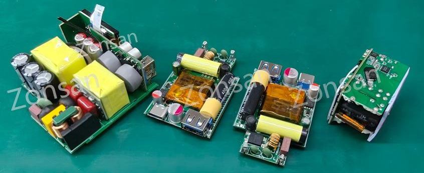
A component may have suitable electrical characteristics but still be incompatible with the existing PCB.
Before treating a replacement as a potential drop-in part, engineers should confirm:
• Package dimensions and tolerances.
• Pinout and pin-function compatibility.
• PCB footprint and solder-pad requirements.
• Component height and clearance.
• Thermal-pad or heatsinking requirements.
• Assembly and inspection constraints.
• A similar-looking package is not proof of pin compatibility.
If the footprint or pinout differs, the change may require PCB modification. That introduces additional work, which may include layout review, prototype production, assembly verification, and further testing.
Mechanical fit also matters outside the PCB. A transformer, connector, or thermal interface material may interact with the enclosure or nearby components. A replacement that fits on the board may still interfere with assembly or alter the product's thermal arrangement.
Step 4 — Evaluate the Effect on Circuit Performance
This is where component evaluation moves beyond datasheet comparison.
The engineer must determine how the alternative is expected to behave in the actual circuit.
Power ICs and controllers
A replacement controller may use a different control strategy, startup sequence, switching frequency, or protection mechanism. Its external component requirements may also differ.
Even if the nominal output power is the same, the circuit may require changes to maintain regulation, stability, or other defined performance characteristics.
MOSFETs and GaN devices
Power switches affect conduction and switching losses. Their behavior can influence efficiency, temperature, EMI, and the operating conditions of surrounding components.
A replacement should be assessed in relation to the actual switching conditions and gate-drive design, not selected solely because its voltage and current ratings are similar.
Capacitors
Capacitors influence different parts of the circuit depending on their location. Changes may affect ripple behavior, filtering, transient response, or lifetime expectations.
The significance of a parameter depends on the circuit role. Engineers should identify which characteristics are critical before deciding whether an alternative is acceptable.
Transformers
Transformer replacement requires attention to the design as a whole. Turns ratio, winding construction, insulation, leakage inductance, magnetizing inductance, parasitic capacitance, and physical construction may all be relevant, depending on the topology.
A transformer with the same nominal output ratings is not necessarily an equivalent replacement.
Step 5 — Review Thermal and EMI Implications
Electrical operation alone may not reveal every consequence of a substitution.
A component that works correctly at room temperature under a short test may behave differently under sustained load or other specified operating conditions.
Engineers should consider whether the proposed change could affect:
• Power losses and temperature rise.
• Heat transfer to nearby components or the enclosure.
• Switching waveforms and ringing.
• Conducted or radiated electromagnetic emissions.
• The performance of filters and surrounding circuits.
• Protection behavior under relevant abnormal conditions.
The appropriate analysis and tests depend on the component and the nature of the change.
For example, a change to a switching device may justify closer attention to switching waveforms and EMI. A change to a mechanical thermal interface may require a different evaluation focused on heat transfer and assembly conditions.
The objective is not to repeat every test regardless of risk. It is to identify the product characteristics that could reasonably be affected and verify them appropriately.
Step 6 — Determine the Required Verification Scope
After the initial technical review, the engineering team should establish what evidence is needed before approving the replacement.
The verification plan should reflect the component's role, the extent of the change, the risks identified, and applicable customer or regulatory requirements.
Depending on the change, verification may include:
1.Document review: Confirm datasheet suitability, pinout, package, ratings, and relevant specifications.
2.Circuit analysis: Assess the effect on operating conditions and surrounding components.
3.Prototype evaluation: Assemble a representative sample using the proposed alternative.
4.Electrical testing: Check the applicable output, regulation, efficiency, startup, load, or protection requirements.
5.Thermal evaluation: Assess temperature behavior under relevant operating conditions.
6.EMI assessment: Determine whether the change warrants additional emissions evaluation.
7.Reliability or stress testing: Apply appropriate checks when the change affects characteristics associated with reliability.
8.Compliance review: Determine whether existing certification or regulatory evidence remains applicable or whether further evaluation is needed.
Not every substitution requires all eight steps. A low-risk change may need a limited evaluation, while a critical component replacement may require broader testing or design modification.
The important requirement is that the scope is justified and documented, rather than decided informally at the purchasing stage.
Step 7 — Control the Change Before Mass Production
A technically promising alternative should not enter production until the required review and approval steps are complete.
The change record should identify the original and proposed components, the reason for the substitution, the evaluation performed, the results, and the applicable approvals.
Depending on the project, customer notification or approval may also be necessary.
The approved BOM, production documentation, and relevant test instructions should be updated so that the factory can identify the correct configuration.
This is particularly important for OEM products. The customer may have approved a sample based on a specific design, and the factory must understand whether the proposed change affects the agreed product configuration or any applicable certification conditions.
For a broader explanation of how design and production revisions are controlled, see Inside ZONSAN's Charger R&D Process.

A Practical Example: Replacing a Power Switch in a GaN Charger
Imagine that a manufacturer needs to replace a power switch used in a 100W GaN charger because the original component has become difficult to source.
A candidate replacement has similar voltage and current ratings and fits within a broadly comparable package.
That is enough to justify further evaluation, but not enough to approve the part.
The engineering team would need to check the relevant switching characteristics, gate-drive requirements, losses, thermal behavior, and compatibility with the existing circuit. Depending on the findings, it may also need to review PCB layout, switching waveforms, EMI performance, and the required verification plan.
If the candidate performs acceptably and the necessary checks are completed, it may be approved for the product. If not, the team may need to consider another part or redesign the affected circuit.
This example illustrates an important distinction: the alternative is not approved because it looks similar. It is approved only when there is sufficient evidence that it meets the applicable requirements.
Common Mistakes When Evaluating Alternative Components
Mistake 1 — Comparing only headline ratings
Two components can share similar voltage, current, or power ratings while differing in parameters that matter to the actual circuit.
Better approach: Identify the critical operating characteristics and compare them under relevant conditions.
Mistake 2 — Assuming a compatible package means electrical equivalence
Physical fit is only one part of suitability. Pin functions, switching behavior, thermal performance, and protection characteristics may differ.
Better approach: Review the datasheet and circuit-level requirements separately.
Mistake 3 — Treating a successful prototype as complete approval
A prototype can reveal important problems, but the required evidence depends on the product's requirements and the extent of the change.
Better approach: Define acceptance criteria and the verification scope before testing begins.
Mistake 4 — Allowing purchasing to make the final technical decision
Purchasing has essential information about cost and availability, but engineering must evaluate technical suitability.
Better approach: Connect sourcing proposals to documented engineering review and the relevant approval process.
Mistake 5 — Forgetting compliance and customer requirements
A component substitution may affect certification evidence or the product configuration approved by the customer. The consequences depend on the actual change and applicable requirements.
Better approach: Include compliance and customer-impact reviews before releasing the revised configuration.
What OEM and ODM Buyers Should Ask
When a buyer's charger project depends on a specific design, the ability to evaluate alternatives can become important throughout the product's commercial life.
Useful questions include:
• Does the factory compare complete technical specifications rather than only headline ratings?
• Can its engineering team explain the relevant differences between the original and proposed components?
• How are prototype testing and verification requirements determined?
• How are component changes recorded in the BOM and production documentation?
• How does the factory evaluate potential effects on thermal performance, EMI, reliability, and compliance?
• What approval is required before a substitute enters mass production?
• Can the factory identify which production batches use the approved component revision?
These questions help buyers understand whether the supplier treats component replacement as an engineering decision or simply as a purchasing adjustment.

Read More
How This Applies to ZONSAN OEM/ODM Projects
ZONSAN manufactures USB-C chargers, GaN chargers, PD/PPS fast chargers, and multi-port charging products for OEM and ODM customers.
Different charger projects can have different power ratings, circuit architectures, port configurations, housing designs, and market requirements. A component substitution therefore needs to be assessed in the context of the particular product rather than approved through a single generic rule.
For customers developing customized chargers, it is useful to establish expectations for component approval, engineering changes, verification, and communication before mass production begins.
The exact evaluation required depends on the component and product design. The objective is to maintain the agreed product requirements while responding responsibly to cost or supply constraints.
Final Thoughts
Alternative component evaluation is an important part of maintaining a charger design throughout its commercial life.
A replacement can offer real benefits: improved availability, lower cost, or reduced dependence on a single source. But those benefits need to be weighed against the electrical, thermal, mechanical, manufacturing, and compliance implications of the change.
The engineering process starts with a clear understanding of the original requirements, continues through technical comparison and appropriate verification, and ends with documented approval before the revised configuration is released.
For charger manufacturers, that discipline helps avoid uncontrolled substitutions. For OEM and ODM buyers, it provides a more reliable basis for maintaining product consistency when supply conditions change.
FAQ: Alternative Component Evaluation for Chargers
Q1. What is alternative component evaluation in charger manufacturing?
It is the engineering process used to determine whether a proposed replacement component is suitable for an existing charger design. It considers relevant datasheet parameters, circuit behavior, mechanical fit, thermal performance, manufacturing requirements, and the necessary verification.
Q2. Can two components with the same voltage and current ratings be used interchangeably?
Not necessarily. They may differ in switching characteristics, thermal behavior, package details, protection functions, or other parameters. Suitability depends on the actual circuit and its requirements.
Q3. Which charger components usually require careful replacement evaluation?
Power ICs, MOSFETs, GaN devices, transformers, capacitors, rectifiers, and protection components can require careful review. The level of evaluation depends on their circuit function and the potential consequences of a change.
Q4. Does every alternative component require a new PCB?
No. A true pin-compatible replacement may fit the existing footprint, but electrical suitability still needs to be established. If the package, pinout, or layout requirements differ, PCB changes may be necessary.
Q5. What tests may be needed after replacing a charger component?
Depending on the change, testing may cover electrical output, regulation, efficiency, startup behavior, protection functions, thermal performance, EMI, or reliability. The verification plan should be based on the affected characteristics and applicable requirements.
Q6. Who should approve an alternative component: purchasing or engineering?
Purchasing can identify cost and availability options, but engineering should evaluate technical suitability. Quality, compliance, and the customer may also need to participate, depending on the product and change.
Q7. Can a component substitution affect charger certification?
Yes, it can, depending on the component, the product's certification basis, and applicable requirements. The manufacturer should assess whether existing evidence remains valid or whether additional testing or review is necessary.
Q8. Why should OEM buyers care about component substitutions?
A substitution can affect the product configuration that the customer originally approved. Clear change control helps buyers understand what is changing, why it is changing, what has been verified, and whether further approval is required.
Reviewer: Zonsan R&D — Luis and David
Second Reviewer: Luke, Ken
Final Review Date: [October 23, 2026]
Imagine that a manufacturer needs to replace a power switch used in a 100W GaN charger because the original component has become difficult to source.
A candidate replacement has similar voltage and current ratings and fits within a broadly comparable package.
That is enough to justify further evaluation, but not enough to approve the part.
The engineering team would need to check the relevant switching characteristics, gate-drive requirements, losses, thermal behavior, and compatibility with the existing circuit. Depending on the findings, it may also need to review PCB layout, switching waveforms, EMI performance, and the required verification plan.
If the candidate performs acceptably and the necessary checks are completed, it may be approved for the product. If not, the team may need to consider another part or redesign the affected circuit.
This example illustrates an important distinction: the alternative is not approved because it looks similar. It is approved only when there is sufficient evidence that it meets the applicable requirements.
Common Mistakes When Evaluating Alternative Components
Mistake 1 — Comparing only headline ratings
Two components can share similar voltage, current, or power ratings while differing in parameters that matter to the actual circuit.
Better approach: Identify the critical operating characteristics and compare them under relevant conditions.
Mistake 2 — Assuming a compatible package means electrical equivalence
Physical fit is only one part of suitability. Pin functions, switching behavior, thermal performance, and protection characteristics may differ.
Better approach: Review the datasheet and circuit-level requirements separately.
Mistake 3 — Treating a successful prototype as complete approval
A prototype can reveal important problems, but the required evidence depends on the product's requirements and the extent of the change.
Better approach: Define acceptance criteria and the verification scope before testing begins.
Mistake 4 — Allowing purchasing to make the final technical decision
Purchasing has essential information about cost and availability, but engineering must evaluate technical suitability.
Better approach: Connect sourcing proposals to documented engineering review and the relevant approval process.
Mistake 5 — Forgetting compliance and customer requirements
A component substitution may affect certification evidence or the product configuration approved by the customer. The consequences depend on the actual change and applicable requirements.
Better approach: Include compliance and customer-impact reviews before releasing the revised configuration.
What OEM and ODM Buyers Should Ask
When a buyer's charger project depends on a specific design, the ability to evaluate alternatives can become important throughout the product's commercial life.
Useful questions include:
• Does the factory compare complete technical specifications rather than only headline ratings?
• Can its engineering team explain the relevant differences between the original and proposed components?
• How are prototype testing and verification requirements determined?
• How are component changes recorded in the BOM and production documentation?
• How does the factory evaluate potential effects on thermal performance, EMI, reliability, and compliance?
• What approval is required before a substitute enters mass production?
• Can the factory identify which production batches use the approved component revision?
These questions help buyers understand whether the supplier treats component replacement as an engineering decision or simply as a purchasing adjustment.
Read More
How This Applies to ZONSAN OEM/ODM Projects
ZONSAN manufactures USB-C chargers, GaN chargers, PD/PPS fast chargers, and multi-port charging products for OEM and ODM customers.
Different charger projects can have different power ratings, circuit architectures, port configurations, housing designs, and market requirements. A component substitution therefore needs to be assessed in the context of the particular product rather than approved through a single generic rule.
For customers developing customized chargers, it is useful to establish expectations for component approval, engineering changes, verification, and communication before mass production begins.
The exact evaluation required depends on the component and product design. The objective is to maintain the agreed product requirements while responding responsibly to cost or supply constraints.
Final Thoughts
Alternative component evaluation is an important part of maintaining a charger design throughout its commercial life.
A replacement can offer real benefits: improved availability, lower cost, or reduced dependence on a single source. But those benefits need to be weighed against the electrical, thermal, mechanical, manufacturing, and compliance implications of the change.
The engineering process starts with a clear understanding of the original requirements, continues through technical comparison and appropriate verification, and ends with documented approval before the revised configuration is released.
For charger manufacturers, that discipline helps avoid uncontrolled substitutions. For OEM and ODM buyers, it provides a more reliable basis for maintaining product consistency when supply conditions change.
FAQ: Alternative Component Evaluation for Chargers
Q1. What is alternative component evaluation in charger manufacturing?
It is the engineering process used to determine whether a proposed replacement component is suitable for an existing charger design. It considers relevant datasheet parameters, circuit behavior, mechanical fit, thermal performance, manufacturing requirements, and the necessary verification.
Q2. Can two components with the same voltage and current ratings be used interchangeably?
Not necessarily. They may differ in switching characteristics, thermal behavior, package details, protection functions, or other parameters. Suitability depends on the actual circuit and its requirements.
Q3. Which charger components usually require careful replacement evaluation?
Power ICs, MOSFETs, GaN devices, transformers, capacitors, rectifiers, and protection components can require careful review. The level of evaluation depends on their circuit function and the potential consequences of a change.
Q4. Does every alternative component require a new PCB?
No. A true pin-compatible replacement may fit the existing footprint, but electrical suitability still needs to be established. If the package, pinout, or layout requirements differ, PCB changes may be necessary.
Q5. What tests may be needed after replacing a charger component?
Depending on the change, testing may cover electrical output, regulation, efficiency, startup behavior, protection functions, thermal performance, EMI, or reliability. The verification plan should be based on the affected characteristics and applicable requirements.
Q6. Who should approve an alternative component: purchasing or engineering?
Purchasing can identify cost and availability options, but engineering should evaluate technical suitability. Quality, compliance, and the customer may also need to participate, depending on the product and change.
Q7. Can a component substitution affect charger certification?
Yes, it can, depending on the component, the product's certification basis, and applicable requirements. The manufacturer should assess whether existing evidence remains valid or whether additional testing or review is necessary.
Q8. Why should OEM buyers care about component substitutions?
A substitution can affect the product configuration that the customer originally approved. Clear change control helps buyers understand what is changing, why it is changing, what has been verified, and whether further approval is required.
Reviewer: Zonsan R&D — Luis and David
Second Reviewer: Luke, Ken
Final Review Date: [October 23, 2026]