Design for Manufacturability in Charger Engineering From PCB Layout to Repeatable Assembly
Provider of Information: Selike and Miller (Engineer)
A charger might perform perfectly during the engineering prototype stage, yet prove difficult to manufacture once it reaches mass production. The issue does not necessarily lie with the circuit design itself.
For instance, certain components may be challenging to place reliably and consistently using surface-mount technology (SMT) equipment; some connectors might be difficult to inspect after assembly; the internal space within the enclosure could be too cramped, complicating the routing of internal wiring; or even a minor shift in the positioning of components could reduce the repeatability of the assembly process.
These problems are easier to address before a design is frozen than after mass production begins.
Design for manufacturability (DFM) in charger engineering is the process of reviewing a charger's electrical design, PCB layout, component selection and mechanical structure to ensure the product can be assembled, inspected and manufactured consistently. DFM does not replace electrical validation or safety testing. It helps engineers identify production difficulties early enough to correct them before they become costly manufacturing problems.
For OEM and ODM buyers, DFM is important because a successful charger design must do more than meet its output specifications. It must also be practical to build repeatedly.
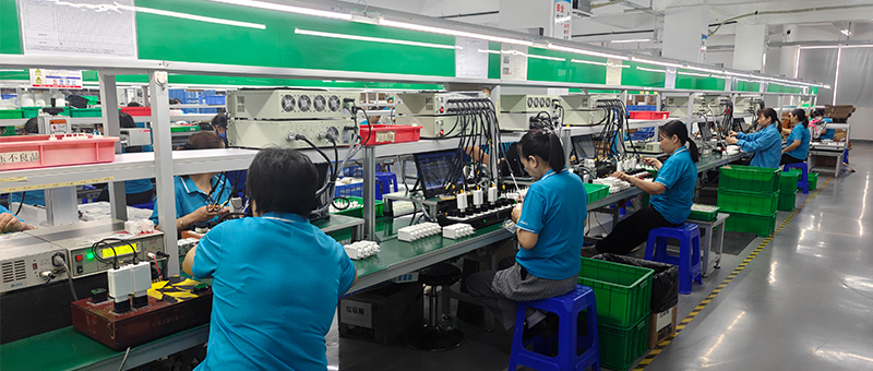
Why DFM Matters for USB-C Charger Production
A charger contains several tightly connected systems: power conversion, control circuitry, protection components, PCB assembly, insulation, connectors and the external housing.
Design decisions made at one stage can have ripple effects on other parts of the system. For instance, adjusting the PCB outline to fit a smaller enclosure might affect component spacing or increase the difficulty of assembly; similarly, relocating a connector might improve the product's appearance, but could simultaneously complicate soldering or inspection processes.
These issues are particularly relevant to compact GaN chargers and high-power USB-C models, where internal space is limited. The challenge is not simply fitting every component onto the board. Engineers also need to consider how the board will be populated, assembled, inspected and installed in the final housing.
DFM brings those manufacturing considerations into the design review rather than leaving them until the first production run.
1. Review the PCB Layout for Assembly
PCB layout affects electrical performance, but it also determines how practical the board is to manufacture.
During a DFM review, engineers consider component spacing, orientation, package selection, soldering access and the relationship between components and the PCB edge. The review should reflect the actual assembly process and the equipment available for the intended production route.
Components placed too close together may create assembly or inspection difficulties. Small parts can be harder to handle consistently, while awkward component orientations may complicate placement or visual verification. This does not mean every charger needs a larger PCB. The goal is to identify whether the layout can be assembled reliably within the product’s physical constraints.
DFM review should also preserve the electrical requirements of the design. Increasing spacing or moving a component cannot be treated as a purely manufacturing change if it affects current paths, EMI behavior, thermal performance or safety-related clearances.
For further background on the relationship between PCB design and charger performance, see Why Charger PCB Design Is Critical for Fast Charging Performance.
2. Choose Components with Production in Mind
Component selection affects more than electrical performance and BOM cost. It also influences assembly consistency, inspection and the stability of the manufacturing process.
Component packaging must align with the intended PCB footprint and assembly process. Its dimensions, pin configuration, and mounting requirements should all be compatible with the production workflow. If a component proves difficult to source consistently, replacing it later will typically entail additional engineering effort.
For a charger manufacturer, component approval should therefore consider both technical suitability and manufacturing practicality.
An alternative component should not be accepted simply because its nominal voltage, current or power rating appears equivalent. Differences in package dimensions, pin arrangement, electrical characteristics or thermal behavior may require a new review and verification.
When component availability changes, the engineering team should assess the effect on the approved design before the replacement is introduced into production. This helps protect consistency between the tested product and the product actually manufactured.
3. Make Assembly Access Part of the Design Review
The internal structure of a charger needs to accommodate both the electronic assembly and the steps required to complete the product.
Engineers should consider how the PCB enters the housing, how internal parts are positioned, whether wiring can be routed without strain, and whether assembly operators or equipment can reach the relevant locations. The design should also allow the required insulation structures and mechanical features to be assembled correctly.
When building a single prototype, engineers can—through precise manipulation and fine-tuning—ensure that all components fit together smoothly; however, this does not mean that the same assembly process remains viable for large-scale mass production.
Repeatable assembly requires defined parts, suitable tolerances and a process that does not depend on unnecessary manual correction. If a design requires operators to repeatedly adjust a component or force parts into position, the design and assembly method should be reviewed.
For OEM projects involving a customized housing, plug structure or port arrangement, these checks should take place before the tooling and production process are finalized.

If critical assembly or performance issues are difficult to detect, then the product cannot be effectively controlled.
DFM should consider how the factory will inspect the PCB, verify electrical output and confirm the finished charger meets its requirements. Depending on the product and process, this may involve automated optical inspection, functional testing, output measurement, protocol verification or other defined checks.
The aim is not to make every inspection point physically accessible at any cost. It is to ensure that the chosen production and testing methods can provide the evidence needed to release the product.
For example, a charger may pass a basic power-on check while still having a defect that only appears under a particular output condition. The test strategy should reflect the risks and functions of the actual design.
It follows that an effective DFM assessment should focus on two related questions: Can the product be assembled in a stable and consistent manner? And can the factory verify that the product's critical characteristics meet specifications before it is shipped?
5. Control Tolerances Between the PCB and Housing
PCBs and enclosures are typically developed as separate components, yet they must be capable of being assembled together to form a complete product.
Factors such as the circuit board outline, connector placement, mounting structures, enclosure dimensions, and mechanical tolerances all influence the final assembly. If the relationships between these elements are not effectively managed, it can lead to issues in the finished product—such as misaligned interfaces, poor mechanical fit, or the subjection of components and solder joints to unintended stress.
This is particularly critical when a charger features a compact enclosure or a customized industrial design. Even minor dimensional variations can affect the fit between multiple internal components. During the design process, engineers should conduct a comprehensive evaluation of all relevant drawings and tolerances, rather than approving the PCB and the enclosure in isolation. If mechanical adjustments alter the fit, the team must assess whether the PCB design, assembly processes, or verification plans require corresponding modifications.
The goal is to make the finished product fit by design, not through repeated manual adjustment on the production line.
6. Consider Manufacturing Risk Before Freezing the Design
Not every DFM issue has the same level of risk. A minor cosmetic concern may be manageable, while a problem affecting insulation, solder-joint quality, connector alignment or test coverage may require immediate attention.
A practical review identifies potential failure points, evaluates their effect on production and product quality, and assigns actions before the design is released.
• Are critical components suitable for the intended SMT process?
• Can the PCB be inspected at the required stages?
• Can the assembly be completed without excessive manual adjustment?
• Are the PCB and housing tolerances compatible?
• Can the required electrical and protocol tests be performed consistently?
• Will an approved component substitution affect the layout or assembly method?
The answers should be documented and reviewed by the relevant engineering and manufacturing personnel. Where a design change is needed, the team should verify that the revision resolves the manufacturing concern without introducing a new electrical or safety issue.
7. Reassess DFM When the Product Changes
DFM is not a one-time check that becomes irrelevant once the first prototype works.
During the development of a charger project, the product may undergo changes. Clients might introduce various requirements—such as modifications to the plug type, enclosure dimensions, interface layout, component selection, or target cost. Even if the product's nominal power rating remains unchanged, any such modification could impact its manufacturing feasibility.
The required review depends on the nature and risk of the change. A cosmetic change may have limited manufacturing impact, while a PCB revision or component replacement may require additional engineering verification.
The team should maintain clear revision records so that the approved design, production documentation and test requirements remain aligned. Production should not rely on an outdated drawing or an unapproved substitution.
For projects moving from prototype to production, DFM should be considered alongside the broader validation process. See DVT and PVT Validation for Chargers for the role of design and production validation.
What OEM Buyers Should Discuss with a Charger Manufacturer
OEM buyers do not need to prescribe every manufacturing detail, but they should share the requirements that influence the design.
These include the target output power, port configuration, enclosure dimensions, plug type, destination markets, certification requirements, target cost and expected production volume. Any special requirements for appearance, packaging or internal structure should also be identified early.
During design review, buyers can ask how the manufacturer evaluates PCB assembly, component availability, mechanical fit, inspection and testing. The purpose is not to demand a particular production method without context. It is to confirm that manufacturing feasibility is considered before the product is committed to mass production.
When a customer requests a design revision, the manufacturer should explain whether it affects component selection, tooling, assembly, testing or validation. Clear communication at this stage helps prevent a small specification change from becoming a larger production issue later.
ZONSAN's Manufacturing Perspective
For a Zonsan fast charger manufacturer, design and manufacturing cannot be treated as completely separate activities. PCB engineering, component selection, housing structure, assembly and verification need to support the same approved product specification.
ZONSAN works with OEM and ODM customers on USB-C charging products with different power ratings, port arrangements, housing requirements and market needs. For each project, the manufacturing approach should be considered alongside the technical specification so that the intended product can be built and checked consistently.
If you are developing a customized charger, share the mechanical requirements and target production needs as early as possible. Reviewing these constraints during engineering is more practical than waiting until production difficulties appear.
Final Thoughts
Design for manufacturability helps turn a working charger design into a product that can be assembled and inspected consistently at scale.
For USB-C and GaN chargers, the key areas include PCB layout, component suitability, assembly access, inspection, mechanical tolerances and revision control. These considerations should be reviewed without compromising the electrical, thermal or safety requirements of the product.
For OEM projects, early DFM review is a practical way to reduce avoidable production problems and improve the transition from engineering samples to repeatable manufacturing.
FAQ
Q1: What is design for manufacturability in charger engineering?
Design for manufacturability is the review of a charger’s design to determine whether it can be assembled, inspected and manufactured consistently while meeting its technical requirements.
Q2: Why is DFM important for GaN chargers?
Compact GaN chargers often have limited internal space. PCB placement, component spacing, housing fit and assembly access must be considered carefully so the product can be manufactured reliably.
Q3: Does DFM replace charger validation?
No. DFM focuses on manufacturing feasibility. Electrical, thermal, safety, protocol and other required verification activities still need to be completed according to the product’s requirements.
Q4: When should DFM begin?
DFM should begin during design development and continue through relevant design reviews and revisions. Identifying manufacturing issues before the design is frozen is generally easier than correcting them after production starts.
Q5: How does PCB layout affect manufacturability?
PCB layout influences component placement, soldering, inspection, assembly access and the relationship between the board and housing. It must also preserve the electrical and safety requirements of the design.
Q6: Can a component replacement affect DFM?
Yes. A replacement may have different dimensions, pin arrangements, placement requirements or electrical characteristics. The change should be reviewed before it is approved for production.
Q7: What should a charger factory check during a DFM review?
The review may cover PCB assembly, component availability, mechanical fit, assembly access, inspection methods, testing requirements and the effect of design changes on production.
Q8: Why should OEM buyers discuss DFM before mass production?
Early discussion helps identify manufacturing constraints before tooling, documentation and production arrangements are finalized. It can also clarify which design changes require further verification.
Reviewer: Zonsan R&D — Luis and David
Second Reviewer: Lucas, Miller
Final Review Date: [October 28, 2026]