Failure Analysis in Charger Manufacturing: How Professional Engineering Teams Identify Root Causes and Prevent Future Defects
Quick Answer
Failure analysis is a structured engineering process used by professional charger manufacturers to identify the root causes of product defects, implement corrective actions and continuously improve product reliability. Instead of simply repairing defective units, engineering teams analyze manufacturing data, testing results and component performance to prevent similar failures from occurring again.
Key Takeaways
1. Failure analysis focuses on identifying root causes, not simply fixing defective products.
2. Modern charger factories combine AOI, ICT, FCT and reliability testing data during investigations.
3. Engineering teams use methods such as 5 Whys, Fishbone Diagrams and Failure Mode Analysis to solve complex manufacturing issues.
4. Effective failure analysis reduces field failures, warranty costs and production variation.
5. Continuous failure analysis strengthens OEM product quality and long-term manufacturing capability.
Introduction
No manufacturing process is perfect.
Even in highly automated production lines, unexpected problems can occasionally occur.
A charger may fail Functional Testing.
A PCB may pass ICT but later fail during Aging Testing.
A USB-C port may work normally in the factory but become unstable after repeated insertion cycles.
The important question is not whether a failure happens.
The more important question is:
How does the engineering team respond when it happens?
Professional manufacturers do not simply replace defective products and continue production.
Instead, every significant failure becomes an opportunity to improve the manufacturing process.
This systematic approach is known as Failure Analysis.
Failure analysis transforms isolated production problems into valuable engineering knowledge.
Rather than treating each defect as an individual event, experienced engineering teams investigate the underlying causes, implement corrective actions and update manufacturing processes to reduce the likelihood of recurrence.
For OEM and ODM customers, this approach contributes to more consistent product quality, lower return rates and greater confidence in long-term manufacturing performance.
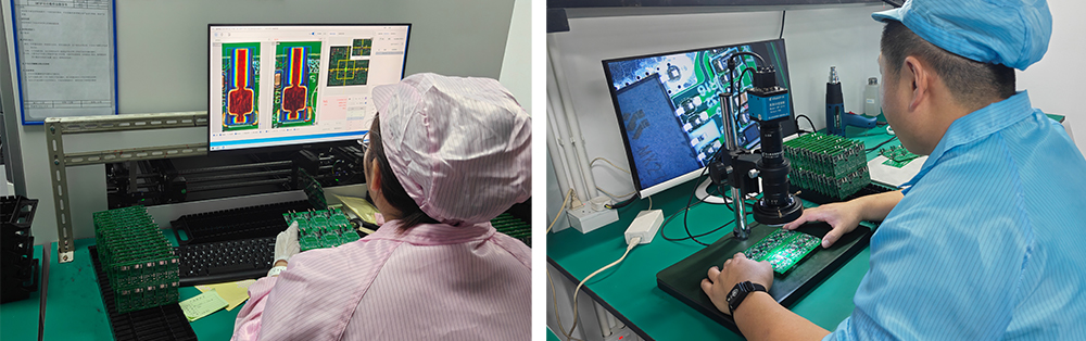
Failure analysis is a structured engineering investigation used to determine why a product failed.
Unlike routine quality inspection, failure analysis begins only after an abnormal condition has been identified.
Its objective is not simply to confirm that a failure exists.
Instead, engineers seek to answer questions such as:
What exactly failed?
When did the failure occur?
Under what operating conditions?
Why did the failure happen?
Could it happen again?
How can future production prevent it?
Every answer should be supported by measurable evidence rather than assumptions.
This evidence may come from production records, testing data, laboratory measurements or component examinations.
Why Failure Analysis Is Essential in USB-C Charger Manufacturing
Modern USB-C chargers integrate high-frequency switching circuits, USB Power Delivery controllers, GaN devices, protection ICs and thermal management systems into extremely compact designs.
As products become smaller and more powerful, manufacturing tolerances become increasingly critical.
Even minor variations may influence:
• Charging stability
• Thermal performance
• USB PD communication
• Long-term durability
• Safety protection behavior
Without systematic failure analysis, manufacturers may only solve the immediate symptom while leaving the underlying cause unresolved.
Over time, similar defects may reappear during future production.
Failure analysis helps engineering teams move from reactive problem solving to proactive quality improvement.
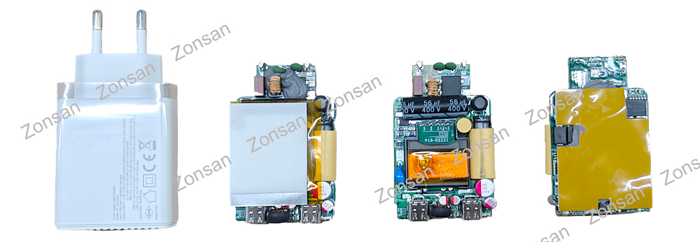
Every production line encounters occasional failures.
Some are simple and easy to correct.
Others require detailed engineering investigation.
Common examples include:
USB PD Communication Failure
The charger powers on normally but cannot complete Power Delivery negotiation with compatible devices.
Possible causes include:
• Controller firmware configuration
• PCB signal integrity
• Component tolerance variation
• Output Voltage Instability
Output voltage fluctuates under load.
Possible contributing factors include:
• Power feedback circuit issues
• Transformer characteristics
• Solder connection quality
• Component aging
Thermal Performance Problems
The charger operates normally during Functional Testing but exceeds temperature limits during Aging Tests.
Engineering teams may investigate:
• Thermal pad placement
• Heat transfer efficiency
• Internal component spacing
• PCB copper layout
Intermittent Connection Issues
Some failures appear only occasionally.
These cases often require extended observation because they may be influenced by vibration, temperature changes or mechanical stress.
The First Step: Collecting Reliable Evidence
One of the biggest mistakes in failure investigation is jumping to conclusions too quickly.
Experienced engineers begin by collecting objective data.
Typical information includes:
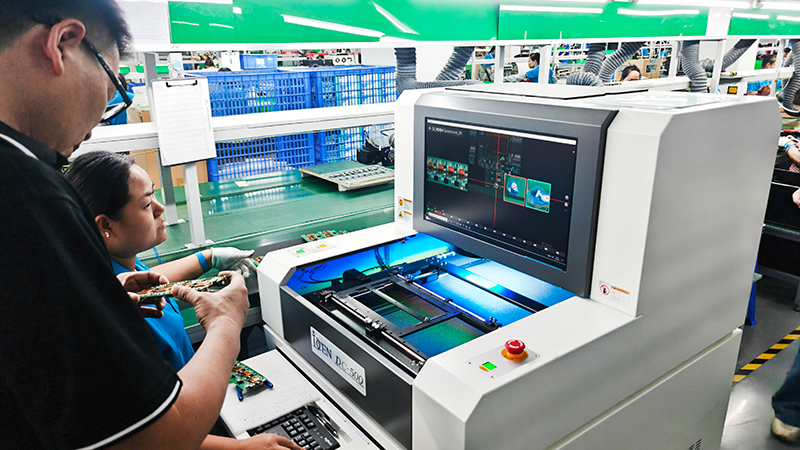
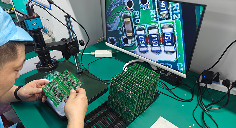
• AOI inspection images
• ICT test records
• Functional Testing logs
• Aging Test results
• Production batch numbers
• Component traceability records
• Environmental testing reports
• Customer feedback (if applicable)
Only after sufficient evidence has been gathered does detailed analysis begin.
Using the 5 Whys to Find the Real Cause
One widely used engineering method is the 5 Whys technique.
Instead of stopping at the first visible problem, engineers repeatedly ask "Why?" until the underlying cause becomes clear.
For example:
Problem: The charger failed Functional Testing.
Why?
The output voltage became unstable.
Why?
Why?
The feedback circuit did not regulate correctly.
Why?
Why?
A resistor value was outside specification.
Why?
Why?
An incorrect component reel was loaded into the SMT machine.
Why?
Material verification procedures were not followed during line setup.
In this example, replacing the resistor fixes one product.
Improving material verification prevents the same issue from affecting future production.
Fishbone Analysis: Looking Beyond a Single Cause
Many production failures result from multiple contributing factors rather than one obvious mistake.
Engineering teams often organize possible causes into categories such as:
1. Materials
2. Machines
3. Methods
4. Manpower
5. Measurement
6. Environment
This approach, commonly known as the Fishbone Diagram or Cause-and-Effect Analysis, encourages broader investigation instead of focusing on a single assumption.
For example, unstable charging performance may involve:
• Component variation
• Equipment calibration
• PCB layout
• Solder quality
• Test conditions
Considering all potential influences helps engineers develop more effective corrective actions.
Verifying the Root Cause Before Taking Corrective Action
Finding a possible cause is only the beginning.
One of the biggest differences between experienced engineering teams and inexperienced ones is that professionals never assume the first explanation is automatically correct.
Every suspected root cause should be verified with objective evidence.
For example, if engineers believe unstable output voltage is caused by a capacitor issue, they should confirm this through controlled testing rather than replacing components based on experience alone.
Typical verification methods include:
• Repeating the failure under the same conditions
• Comparing failed units with qualified products
• Measuring electrical characteristics
• Substituting components for comparison
• Reviewing production data from different batches
Only after the suspected cause has been confirmed should corrective actions be introduced into production.
This approach prevents unnecessary process changes and avoids creating new problems while attempting to solve existing ones.
Why?
Material verification procedures were not followed during line setup.
In this example, replacing the resistor fixes one product.
Improving material verification prevents the same issue from affecting future production.
Fishbone Analysis: Looking Beyond a Single Cause
Many production failures result from multiple contributing factors rather than one obvious mistake.
Engineering teams often organize possible causes into categories such as:
1. Materials
2. Machines
3. Methods
4. Manpower
5. Measurement
6. Environment
This approach, commonly known as the Fishbone Diagram or Cause-and-Effect Analysis, encourages broader investigation instead of focusing on a single assumption.
For example, unstable charging performance may involve:
• Component variation
• Equipment calibration
• PCB layout
• Solder quality
• Test conditions
Considering all potential influences helps engineers develop more effective corrective actions.
Verifying the Root Cause Before Taking Corrective Action
Finding a possible cause is only the beginning.
One of the biggest differences between experienced engineering teams and inexperienced ones is that professionals never assume the first explanation is automatically correct.
Every suspected root cause should be verified with objective evidence.
For example, if engineers believe unstable output voltage is caused by a capacitor issue, they should confirm this through controlled testing rather than replacing components based on experience alone.
Typical verification methods include:
• Repeating the failure under the same conditions
• Comparing failed units with qualified products
• Measuring electrical characteristics
• Substituting components for comparison
• Reviewing production data from different batches
Only after the suspected cause has been confirmed should corrective actions be introduced into production.
This approach prevents unnecessary process changes and avoids creating new problems while attempting to solve existing ones.
From Root Cause to CAPA: Turning Analysis into Action
Identifying the reason for a failure is valuable, but it only creates real business value when the findings are translated into improvements.
Professional manufacturers generally follow a Corrective and Preventive Action (CAPA) process.
The workflow is straightforward:
1. Detect the failure.
2. Confirm the root cause.
3. Implement corrective action.
4. Verify that the correction is effective.
5. Introduce preventive measures to stop similar issues from recurring.
For example, if repeated ICT failures are traced to inconsistent solder paste printing, the solution may include:
• Updating printer parameters
• Improving stencil cleaning frequency
• Retraining production operators
• Adding additional SPI verification
• Revising process documentation
The objective is not simply to repair defective products, but to improve the entire manufacturing process.
How Failure Analysis Improves Future Product Design
Failure analysis does not only benefit production.
It also provides valuable feedback for product development.
When engineering teams repeatedly encounter the same issue, it may indicate that the product design itself can be improved.
Examples include:
• Increasing creepage and clearance distances.
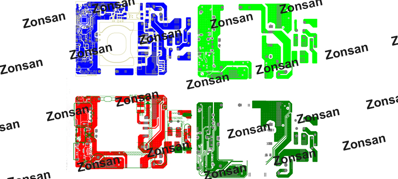
• Optimizing PCB copper distribution for better heat dissipation.
• Selecting components with wider operating margins.
• Improving airflow inside compact charger housings.
• Relocating heat-sensitive components away from high-temperature areas.
Over time, these improvements make future charger generations easier to manufacture and more reliable in daily use.
This is why experienced OEM manufacturers encourage close collaboration between R&D engineers and manufacturing engineers.
A Typical Engineering Example
Consider a situation where several chargers fail the Aging Test after operating continuously for many hours.
Initial observations suggest excessive internal temperature.
Rather than immediately replacing components, engineers begin a structured investigation.
The process may include:
• Reviewing AOI inspection images.
• Comparing ICT measurement data.
• Repeating Functional Testing.
• Recording thermal images during operation.
• Measuring temperatures at different locations inside the charger.
• Comparing multiple production batches.
After analysis, the team discovers that the thermal interface material between the power device and the heatsink was applied inconsistently during assembly.
Although every charger passed Functional Testing, prolonged operation exposed the variation in heat transfer efficiency.
Instead of simply replacing thermal material in the failed products, the factory updates:
• Assembly work instructions.
• Dispensing equipment settings.
• Process inspection standards.
• Operator training procedures.
As a result, the issue is eliminated across future production.
This example illustrates an important principle:
Failure analysis is most valuable when it improves the manufacturing system—not just the individual product.
Common Mistakes During Failure Investigation
Even experienced factories can reduce the effectiveness of failure analysis if the investigation process is not managed carefully.
Some common mistakes include:
Assuming Instead of Measuring
Personal experience is valuable, but engineering decisions should always be supported by measurable evidence.
Focusing Only on Symptoms
Replacing a damaged component may restore functionality, but it does not explain why the component failed.
Without identifying the underlying cause, similar failures may return.
Ignoring Production Data
Modern production lines generate valuable information through AOI, ICT, FCT and traceability systems.
Ignoring this data means missing opportunities to identify recurring patterns.
Working in Isolation
Complex manufacturing problems often require collaboration between different departments.
Design engineers, manufacturing engineers, quality engineers and suppliers may all contribute different perspectives that lead to a more accurate conclusion.
Why OEM and ODM Customers Should Care About Failure Analysis
From a buyer's perspective, failure analysis is rarely visible.
Customers usually see only the finished charger.
However, behind every reliable product is a manufacturing team capable of learning from every defect.
A mature failure analysis system helps OEM and ODM customers by:
• Improving product consistency.
• Reducing field failure rates.
• Supporting continuous product improvement.
• Lowering warranty and return costs.
• Increasing confidence in long-term manufacturing partnerships.
For companies building their own brands, these benefits directly influence customer satisfaction and market reputation.
Continuous Improvement Is the Real Goal
Some people view failure analysis as a process used only when something goes wrong.
Professional manufacturers see it differently.
Every production issue provides an opportunity to improve products, manufacturing processes and engineering knowledge.
Over months and years, these small improvements accumulate.
The result is not only fewer defects but also stronger engineering capability, more stable production and greater customer confidence.
In this sense, failure analysis is not about failures alone.
It is about building a manufacturing system that becomes more reliable with every production cycle.
Final Thoughts
Quality is not created by inspection alone.
It is built through continuous learning.
Failure analysis allows manufacturers to move beyond simply identifying defective products.
By understanding why problems occur, verifying root causes and implementing effective corrective actions, engineering teams continuously strengthen both product reliability and manufacturing performance.
For professional USB-C charger manufacturers, this process forms an essential link between production, engineering and quality management.
Combined with AOI, ICT, Functional Testing, Aging Tests and process control, failure analysis helps transform individual manufacturing experiences into long-term engineering excellence.
Frequently Asked Questions (FAQ)
Q1: What is failure analysis in charger manufacturing?
Failure analysis is a structured engineering process used to determine the root cause of product or manufacturing defects and implement corrective and preventive actions.
Q2: Why is failure analysis important for OEM projects?
It helps manufacturers reduce recurring defects, improve production consistency and enhance long-term product reliability.
Q3: What information is typically used during failure analysis?
Engineering teams may review AOI images, ICT records, Functional Testing results, Aging Test data, production traceability records and laboratory measurements.
Q4: What is the difference between corrective action and preventive action?
Corrective action addresses an existing problem, while preventive action modifies processes to reduce the likelihood of similar issues occurring in future production.
Q5: Does every production failure require a complete investigation?
Not always. Investigation depth usually depends on the severity, frequency and potential impact of the issue. Repeated or critical failures generally require more comprehensive root cause analysis.
Q6: Can failure analysis improve future product designs?
Yes. Findings from production often help engineering teams optimize PCB layouts, thermal design, component selection and manufacturing processes for future products.
Q7: Which engineering methods are commonly used during failure analysis?
Common approaches include the 5 Whys, Fishbone (Cause-and-Effect) Analysis, Pareto Analysis, Failure Mode and Effects Analysis (FMEA) and statistical process evaluation.
Q8: How does failure analysis support continuous improvement?
By identifying recurring issues, verifying root causes and updating manufacturing processes, failure analysis creates a continuous feedback loop that improves both product quality and production efficiency.
Recommended
• Functional Testing (FCT) in USB-C Charger Manufacturing: How Professional Factories Verify Real Charging Performance Before Shipment.↗
• How ICT Testing Ensures PCB Reliability in USB-C Charger Manufacturing.↗
• How Chargers Go Through Aging Tests Before Shipping: Why Burn-In Testing Is Essential for Long-Term Reliability.↗
• Gan 1 vs Gan 2 vs Gan 3.↗