How ICT Testing Ensures PCB Reliability in USB-C Charger Manufacturing
Quick Answer
ICT (In-Circuit Testing) is an automated electrical testing method used to verify PCB performance during electronics manufacturing. In USB-C charger production, ICT checks electrical connections, component values, circuit continuity and potential assembly defects before products move to final assembly and functional testing.
Key Takeaways
• ICT verifies the electrical integrity of PCB assemblies.
• It detects hidden defects that visual inspection cannot identify.
• ICT works together with AOI, FCT and aging tests to create a complete quality control system.
• Professional charger manufacturers use ICT data to improve production consistency.
• ICT is especially important for compact high-power chargers with complex PCB designs.
Introduction
Modern USB-C chargers are becoming smaller, faster and more intelligent.
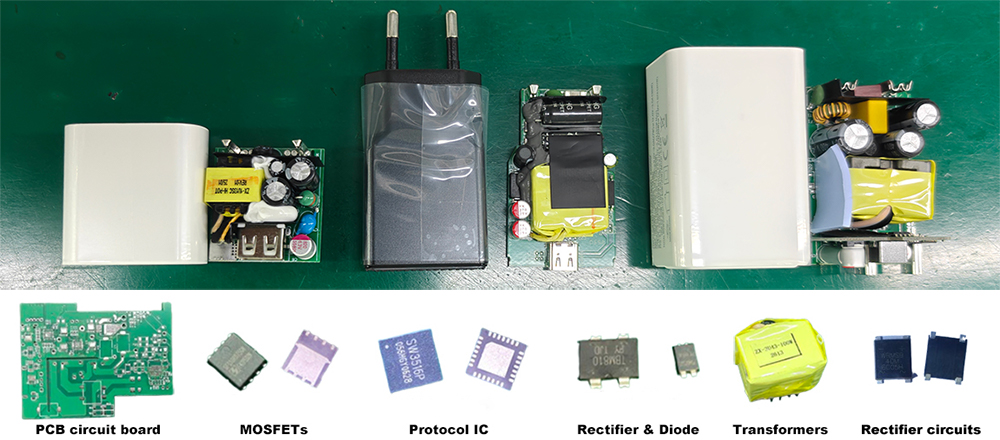
A compact GaN charger may contain:
• Power conversion circuits
• USB PD controllers
• Protection ICs
• Switching MOSFETs
• Feedback circuits
• Communication components
• Multiple voltage regulation stages
From the outside, the final product may look simple.
However, inside the charger, hundreds of electrical connections must work together precisely.
A PCB can appear visually perfect and still contain hidden electrical problems.
For example:
• A solder joint may look acceptable but have poor electrical connection.
• A resistor may be installed correctly but have the wrong value.
• A circuit path may contain a hidden open connection.
• A component may be damaged during assembly.
These problems cannot always be detected through visual inspection alone.
This is where In-Circuit Testing (ICT) becomes essential.
ICT provides manufacturers with a deeper understanding of PCB electrical performance before the board becomes part of a finished charger.
For OEM and ODM customers, this means fewer hidden defects, improved reliability and better production consistency.
In-Circuit Testing is an automated electrical inspection method that evaluates individual circuits and components on a PCB assembly.
Unlike AOI, which mainly checks physical appearance, ICT measures electrical characteristics.
During ICT testing, a specially designed fixture connects with specific test points on the PCB.
The system then applies electrical signals and measures responses from different parts of the circuit.
Depending on the product design, ICT can evaluate:
• Resistance values
• Capacitance values
• Component presence
• Circuit continuity
• Short circuits
• Open circuits
• Diode characteristics
• Certain semiconductor functions
The goal is simple:
Verify that the PCB has been assembled electrically according to the original design.
Why USB-C Chargers Need ICT Testing
Not all electronic products require the same level of inspection.
However, modern fast chargers have become significantly more complex.
A traditional low-power adapter may contain relatively simple circuits.
A modern 65W, 100W or 140W GaN charger involves much higher integration.
For example:
A PD charger must correctly communicate with connected devices.
A power management circuit must regulate different output voltages.
Protection systems must respond correctly under abnormal conditions.
Small electrical errors can affect:
• Charging stability
• Power efficiency
• Device compatibility
• Long-term reliability
ICT helps identify these issues before the charger reaches final production stages.
Where ICT Fits in the Charger Manufacturing Process
Professional charger manufacturing uses multiple inspection layers.
Each test has a different purpose.
A typical quality control process may include:
1. SPI Inspection
Checks solder paste printing quality before component placement.
2. SMT Assembly
Components are accurately placed onto the PCB.
3. Reflow Soldering
Components are permanently connected through soldering.
4. AOI Inspection
Checks visible assembly quality:
• Component placement
• Solder joints
• Missing parts
5. ICT Testing
Checks electrical integrity:
• Circuit connections
• Component values
• Electrical characteristics
6. Functional Testing (FCT)
Verifies actual charger operation.
7. Safety Testing
Including:
• Hi-Pot testing
• Grounding verification
• Leakage current measurement
8. Aging Testing
Simulates long-term operation.
This layered approach prevents manufacturers from relying on a single inspection method.
Instead, each stage addresses a different potential risk.
What Defects Can ICT Detect?
One of the biggest advantages of ICT is its ability to identify hidden electrical problems.
Common ICT-detectable defects include:
Open Circuit Failures
An open circuit occurs when an electrical connection is interrupted.
Possible causes include:
• Poor soldering
• Damaged PCB traces
• Component connection issues
Although the PCB may look normal, electrical current cannot flow correctly.
ICT can quickly identify these problems.
Short Circuit Problems
Short circuits occur when unintended connections exist between electrical paths.
They may cause:
• Abnormal current flow
• Component damage
• Safety risks
ICT testing helps detect these issues before power is applied to finished products.
Incorrect Component Values
A component may be physically installed correctly but have the wrong specification.
Examples:
• Incorrect resistor value
• Wrong capacitor rating
• Incorrect component placement
These errors can affect charging performance and efficiency.
Why ICT Data Matters for Manufacturing Improvement
ICT is not only a pass/fail inspection.
The data generated during testing provides valuable information about production quality.
Engineering teams can analyze:
• Failure frequency
• Defect categories
• Production line differences
• Component-related issues
For example:
If the same resistor value error appears repeatedly, engineers can investigate:
• Component feeding accuracy
• Supplier issues
• SMT programming errors
This transforms ICT from a simple inspection step into a continuous improvement tool.
Why ICT Fixture Design Matters
When people first hear about In-Circuit Testing, they often focus on the testing software or measurement equipment. However, one of the most critical elements of ICT is something far less visible—the test fixture.
An ICT fixture is a custom-designed platform that connects the testing system to specific points on the PCB. Hundreds of precision probes, often called bed-of-nails probes, make contact with designated test pads simultaneously.
The quality of the fixture directly affects the quality of the inspection.
If contact pressure is inconsistent or probe alignment is inaccurate, measurement results may become unreliable, even when the PCB itself is perfectly assembled.
For this reason, professional charger manufacturers treat ICT fixture development as an engineering project rather than simply purchasing standard equipment.
A well-designed fixture offers several advantages:
• Stable electrical contact
• Fast testing cycles
• Repeatable measurement accuracy
• Lower maintenance requirements
• Reduced false failures during production
For high-volume USB-C charger manufacturing, investing in high-quality ICT fixtures improves both efficiency and production consistency.
ICT vs AOI vs Functional Testing
Each inspection method answers a different engineering question.
Understanding their differences helps explain why professional factories never rely on only one type of test.
Inspection Method Primary Purpose Detects
AOI (Automated Optical Inspection) Visual assembly verification Missing components, incorrect placement, solder defects
ICT (In-Circuit Testing) Electrical integrity verification Open circuits, short circuits, incorrect component values, continuity issues
FCT (Functional Testing) Product operation verification Charging performance, USB PD communication, output stability, protection functions
Think of it this way:
• AOI asks: Was the PCB assembled correctly?
• ICT asks: Is the PCB electrically correct?
• FCT asks: Does the finished charger actually work as intended?
Each stage complements the others.
Skipping any one of them increases the possibility that defects will escape into later production stages or, worse, reach the customer.
Why ICT Is More Challenging Than Many People Expect
At first glance, ICT appears to be a straightforward automated process.
In reality, implementing an effective ICT system requires considerable engineering experience.
Every charger model requires:
• Dedicated test points in the PCB design
• Customized fixtures
• Test software development
• Measurement parameter optimization
• Regular calibration
As charger designs become more compact, engineers have fewer available test points.
Modern GaN chargers often use multilayer PCBs with densely packed components, making fixture design increasingly complex.
Because of these challenges, experienced engineering teams work closely with PCB designers from the earliest development stages to ensure the product remains testable throughout mass production.
The Limitations of ICT Testing
Although ICT is a powerful quality control method, it is not designed to solve every manufacturing challenge.
Understanding its limitations helps manufacturers build a more complete testing strategy.
For example, ICT generally cannot evaluate:
• Long-term thermal stability
• USB Power Delivery protocol negotiation
• PPS or AVS charging behavior
• Charging efficiency under different loads
• Heat generation during extended operation
• Product durability after aging
These characteristics require additional evaluations such as:
• Functional Testing (FCT)
• Hi-Pot Testing
• Aging Testing
• Environmental Testing
• Thermal Performance Evaluation
Professional factories therefore combine multiple inspection methods rather than expecting ICT to provide every answer.
How Professional Manufacturers Build a Multi-Layer Quality Control System
One of the defining characteristics of experienced charger manufacturers is that they never depend on a single inspection stage.
Instead, quality is verified progressively throughout production.
A typical quality flow may look like this:
SPI → AOI → ICT → FCT → Hi-Pot → Aging Test → Environmental Validation → Final Inspection
Each process targets different risks.
For example:
• SPI helps prevent solder paste defects before assembly.
• AOI identifies visible manufacturing defects.
• ICT verifies electrical integrity.
• FCT confirms charging performance.
• Hi-Pot validates electrical safety.
• Aging testing evaluates long-term stability.
• Environmental testing confirms reliability under different climate conditions.
This layered verification strategy greatly reduces the probability of hidden defects reaching customers.
Common Misconceptions About ICT
Misconception 1: ICT Can Replace Functional Testing
It cannot.
A PCB may pass every electrical measurement yet still fail to negotiate USB PD correctly during actual charging.
Functional testing remains essential.
Misconception 2: Every PCB Can Easily Be Tested by ICT
Not necessarily.
Modern compact charger designs require careful planning during PCB layout to ensure adequate access for test probes.
Good testability begins during product design.
Misconception 3: ICT Only Finds Assembly Problems
While assembly issues are common findings, ICT also identifies incorrect component values, hidden electrical faults and connectivity problems that visual inspection cannot detect.
Misconception 4: ICT Is Only Necessary for High-End Products
As charging technologies become increasingly sophisticated, electrical verification has become valuable across many charger categories—not only premium products.
For manufacturers supplying OEM and ODM customers, ICT has become an important part of maintaining consistent quality.
Final Thoughts
Visual inspection tells only part of the story.
A PCB that appears flawless may still contain electrical defects capable of affecting charging performance or long-term reliability.
In-Circuit Testing bridges this gap by verifying the electrical integrity of every assembled circuit board before final assembly.
For professional USB-C charger manufacturers, ICT is far more than a production checkpoint.
It provides engineering insight, supports continuous process improvement and strengthens confidence in every product leaving the factory.
Combined with AOI, Functional Testing, Hi-Pot Testing and Aging Tests, ICT forms a key part of a comprehensive quality assurance system designed to deliver reliable charging products to customers worldwide.
Read More
Frequently Asked Questions (FAQ)
Q1: What is ICT testing in charger manufacturing?
ICT (In-Circuit Testing) verifies the electrical integrity of PCB assemblies by measuring component values, circuit continuity and electrical connections before final assembly.
Q2: How is ICT different from AOI?
AOI inspects the physical appearance of the PCB, while ICT evaluates its electrical performance.
Q3: Can ICT detect faulty components?
Yes. ICT can identify incorrect component values, open circuits, short circuits and many electrical faults that are not visible during visual inspection.
Q4: Why is ICT important for GaN chargers?
GaN chargers contain highly integrated circuits and compact PCB layouts, making accurate electrical verification essential for maintaining consistent product quality.
Q5: Does every charger require ICT?
The testing strategy depends on product design, production volume and customer requirements. Many professional manufacturers include ICT as part of their standard quality control process for complex charger products.
Q6: Can ICT replace Functional Testing?
No. ICT verifies electrical integrity, while Functional Testing confirms that the finished charger performs correctly during actual operation.
Q7: What equipment is required for ICT?
An ICT system typically includes a programmable tester, custom fixture, precision probes, measurement software and engineering support for fixture and program development.
Q8: How does ICT improve manufacturing quality?
ICT detects hidden electrical defects early, reduces downstream failures, improves production consistency and provides valuable data for continuous process improvement.
Recommended
• Why AOI Inspection Is Essential for Modern USB-C Charger Manufacturing.↗
• Environmental Testing for USB-C Power Adapters: How Professional Manufacturers Verify Reliability in Real-World Conditions.↗
• Understanding Hi-Pot Testing for USB-C Chargers: How Professional Manufacturers Verify Electrical Safety Before Shipment.↗
• IPC Standards for Electronics Manufacturing.↗
• IEEE – Electronics Testing and Measurement Resources.↗
Each inspection method answers a different engineering question.
Understanding their differences helps explain why professional factories never rely on only one type of test.
Inspection Method Primary Purpose Detects
AOI (Automated Optical Inspection) Visual assembly verification Missing components, incorrect placement, solder defects
ICT (In-Circuit Testing) Electrical integrity verification Open circuits, short circuits, incorrect component values, continuity issues
FCT (Functional Testing) Product operation verification Charging performance, USB PD communication, output stability, protection functions
Think of it this way:
• AOI asks: Was the PCB assembled correctly?
• ICT asks: Is the PCB electrically correct?
• FCT asks: Does the finished charger actually work as intended?
Each stage complements the others.
Skipping any one of them increases the possibility that defects will escape into later production stages or, worse, reach the customer.
Why ICT Is More Challenging Than Many People Expect
At first glance, ICT appears to be a straightforward automated process.
In reality, implementing an effective ICT system requires considerable engineering experience.
Every charger model requires:
• Dedicated test points in the PCB design
• Customized fixtures
• Test software development
• Measurement parameter optimization
• Regular calibration
As charger designs become more compact, engineers have fewer available test points.
Modern GaN chargers often use multilayer PCBs with densely packed components, making fixture design increasingly complex.
Because of these challenges, experienced engineering teams work closely with PCB designers from the earliest development stages to ensure the product remains testable throughout mass production.
The Limitations of ICT Testing
Although ICT is a powerful quality control method, it is not designed to solve every manufacturing challenge.
Understanding its limitations helps manufacturers build a more complete testing strategy.
For example, ICT generally cannot evaluate:
• Long-term thermal stability
• USB Power Delivery protocol negotiation
• PPS or AVS charging behavior
• Charging efficiency under different loads
• Heat generation during extended operation
• Product durability after aging
These characteristics require additional evaluations such as:
• Functional Testing (FCT)
• Hi-Pot Testing
• Aging Testing
• Environmental Testing
• Thermal Performance Evaluation
Professional factories therefore combine multiple inspection methods rather than expecting ICT to provide every answer.
How Professional Manufacturers Build a Multi-Layer Quality Control System
One of the defining characteristics of experienced charger manufacturers is that they never depend on a single inspection stage.
Instead, quality is verified progressively throughout production.
A typical quality flow may look like this:
SPI → AOI → ICT → FCT → Hi-Pot → Aging Test → Environmental Validation → Final Inspection
Each process targets different risks.
For example:
• SPI helps prevent solder paste defects before assembly.
• AOI identifies visible manufacturing defects.
• ICT verifies electrical integrity.
• FCT confirms charging performance.
• Hi-Pot validates electrical safety.
• Aging testing evaluates long-term stability.
• Environmental testing confirms reliability under different climate conditions.
This layered verification strategy greatly reduces the probability of hidden defects reaching customers.
Common Misconceptions About ICT
Misconception 1: ICT Can Replace Functional Testing
It cannot.
A PCB may pass every electrical measurement yet still fail to negotiate USB PD correctly during actual charging.
Functional testing remains essential.
Misconception 2: Every PCB Can Easily Be Tested by ICT
Not necessarily.
Modern compact charger designs require careful planning during PCB layout to ensure adequate access for test probes.
Good testability begins during product design.
Misconception 3: ICT Only Finds Assembly Problems
While assembly issues are common findings, ICT also identifies incorrect component values, hidden electrical faults and connectivity problems that visual inspection cannot detect.
Misconception 4: ICT Is Only Necessary for High-End Products
As charging technologies become increasingly sophisticated, electrical verification has become valuable across many charger categories—not only premium products.
For manufacturers supplying OEM and ODM customers, ICT has become an important part of maintaining consistent quality.
Final Thoughts
Visual inspection tells only part of the story.
A PCB that appears flawless may still contain electrical defects capable of affecting charging performance or long-term reliability.
In-Circuit Testing bridges this gap by verifying the electrical integrity of every assembled circuit board before final assembly.
For professional USB-C charger manufacturers, ICT is far more than a production checkpoint.
It provides engineering insight, supports continuous process improvement and strengthens confidence in every product leaving the factory.
Combined with AOI, Functional Testing, Hi-Pot Testing and Aging Tests, ICT forms a key part of a comprehensive quality assurance system designed to deliver reliable charging products to customers worldwide.
Read More
Frequently Asked Questions (FAQ)
Q1: What is ICT testing in charger manufacturing?
ICT (In-Circuit Testing) verifies the electrical integrity of PCB assemblies by measuring component values, circuit continuity and electrical connections before final assembly.
Q2: How is ICT different from AOI?
AOI inspects the physical appearance of the PCB, while ICT evaluates its electrical performance.
Q3: Can ICT detect faulty components?
Yes. ICT can identify incorrect component values, open circuits, short circuits and many electrical faults that are not visible during visual inspection.
Q4: Why is ICT important for GaN chargers?
GaN chargers contain highly integrated circuits and compact PCB layouts, making accurate electrical verification essential for maintaining consistent product quality.
Q5: Does every charger require ICT?
The testing strategy depends on product design, production volume and customer requirements. Many professional manufacturers include ICT as part of their standard quality control process for complex charger products.
Q6: Can ICT replace Functional Testing?
No. ICT verifies electrical integrity, while Functional Testing confirms that the finished charger performs correctly during actual operation.
Q7: What equipment is required for ICT?
An ICT system typically includes a programmable tester, custom fixture, precision probes, measurement software and engineering support for fixture and program development.
Q8: How does ICT improve manufacturing quality?
ICT detects hidden electrical defects early, reduces downstream failures, improves production consistency and provides valuable data for continuous process improvement.
Recommended
• Why AOI Inspection Is Essential for Modern USB-C Charger Manufacturing.↗
• Environmental Testing for USB-C Power Adapters: How Professional Manufacturers Verify Reliability in Real-World Conditions.↗
• Understanding Hi-Pot Testing for USB-C Chargers: How Professional Manufacturers Verify Electrical Safety Before Shipment.↗
• IPC Standards for Electronics Manufacturing.↗
• IEEE – Electronics Testing and Measurement Resources.↗