How Transformer Design Determines Charger Efficiency: The Engineering Behind Every Fast Charger
Quick Answer (Featured Snippet)
The transformer is one of the most important components inside a USB-C charger. It transfers energy from the high-voltage primary circuit to the low-voltage output while providing electrical isolation. Its design directly affects charging efficiency, operating temperature, electromagnetic interference (EMI), power density and long-term reliability. In modern GaN chargers, transformer optimization is one of the key factors that enables smaller size and higher power output.
Key Takeaways
Every isolated fast charger relies on a high-frequency transformer.
Transformer design affects efficiency, heat generation and charging stability.
Core material, winding structure and operating frequency all influence performance.
Poor transformer design can increase energy loss, noise and operating temperature.
Professional charger manufacturers often spend multiple prototype iterations optimizing transformer performance before mass production.
Introduction
If you open a modern USB-C charger, you'll probably notice several familiar components.
There are capacitors, integrated circuits, USB-C controllers and, in newer models, compact GaN power devices.
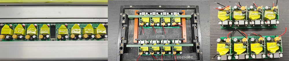
Near the center of the PCB, however, you'll almost always find a small yellow or black component wrapped in insulating tape.
That component is the transformer.
Although it occupies only a small portion of the circuit board, it performs one of the most demanding tasks inside the entire charger.
Without it, a typical AC-powered USB-C charger simply could not operate safely.
More importantly, the quality of its design has a direct influence on how efficiently the charger converts power, how much heat it generates, how quietly it operates and how reliably it performs over thousands of charging cycles.
For engineers, the transformer is never just another component purchased from a supplier.
It is a custom-designed energy conversion device that must be carefully matched to the entire power architecture.
This is why transformer development often continues throughout multiple prototype stages, even after the schematic and PCB layout have largely been finalized.
Why Every Fast Charger Needs a Transformer
One of the most important jobs inside any wall charger is converting mains electricity into safe, stable low-voltage DC power.
Household electricity arrives as high-voltage alternating current.
Your smartphone, tablet or laptop, however, requires carefully regulated low-voltage direct current.
Simply reducing the voltage is not enough.
The charger must also provide electrical isolation between the mains supply and the USB output to protect users from dangerous voltages.
This is where the transformer becomes essential.
Inside a modern isolated switching power supply, the transformer performs two critical functions simultaneously:
• Transfers electrical energy from the primary circuit to the secondary circuit.
• Maintains safe electrical isolation between the AC input and the USB output.
Unlike the large iron-core transformers found in older electronic equipment, fast chargers use high-frequency transformers.
Operating at switching frequencies that may exceed hundreds of kilohertz allows these transformers to become dramatically smaller while maintaining excellent power conversion capability.
Without high-frequency operation, today's compact 65W, 100W and 140W chargers simply would not be possible.
The Transformer Does More Than Transfer Energy
Many people assume the transformer's only purpose is to reduce voltage.
In reality, it influences nearly every aspect of charger performance.
A well-designed transformer helps:
• Improve overall conversion efficiency.
• Reduce internal heat generation.
• Lower acoustic noise during operation.
• Minimize electromagnetic interference.
• Improve voltage regulation.
• Support stable USB Power Delivery output.
• Increase long-term reliability.
Conversely, an under-optimized transformer can create problems throughout the entire power supply.
For example, excessive leakage inductance may increase switching losses.
Poor winding techniques can increase copper loss.
An unsuitable magnetic core may generate unnecessary heat.
These issues often appear during engineering validation rather than in theoretical calculations.
This is why transformer optimization is considered one of the most experience-dependent areas of charger development.
Understanding the Three Main Parts of a Charger Transformer
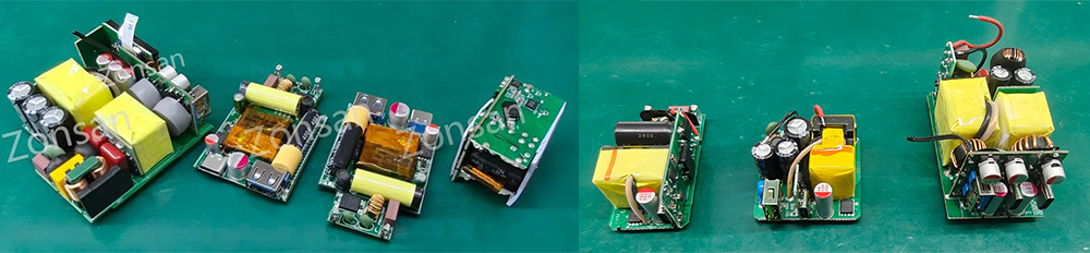
Although transformer designs vary depending on power level and topology, most high-frequency transformers share three essential elements.
Magnetic Core
The magnetic core forms the foundation of the transformer.
Rather than conducting electricity, it guides the magnetic field created by the switching circuit.
Modern USB-C chargers typically use ferrite cores because they perform efficiently at high frequencies while minimizing core losses.
Selecting the correct core size involves balancing multiple design goals.
A larger core may reduce magnetic saturation and improve efficiency, but it also increases the overall charger size.
A smaller core helps achieve compact products but requires more careful thermal management.
Finding the optimal balance is one of the first engineering decisions in transformer design.
Primary and Secondary Windings
Copper windings are wrapped around the magnetic core to transfer energy.
The primary winding receives high-frequency electrical pulses generated by the switching circuit.
These pulses create a changing magnetic field inside the ferrite core.
The secondary winding converts that magnetic field back into electrical energy suitable for powering USB devices.
The relationship between these windings influences output voltage, current capability and efficiency.
However, transformer design is far more complex than simply selecting a turns ratio.
Engineers must also consider:
• Wire diameter
• Winding sequence
• Layer arrangement
• Insulation requirements
• Leakage inductance
• Manufacturing repeatability
Even small adjustments to winding structure can noticeably change electrical performance.
Insulation System
Safety standards require complete electrical isolation between the high-voltage primary side and the low-voltage secondary side.
This isolation is achieved through carefully selected insulation materials and construction techniques.
Professional transformer manufacturers pay close attention to insulation thickness, tape placement, margin spacing and winding arrangement to ensure compliance with international safety standards.
Reliable insulation is one reason properly designed chargers remain safe throughout years of daily use.
Why Transformer Efficiency Matters More in GaN Chargers
One of the biggest advantages of GaN technology is its ability to switch at much higher frequencies than conventional silicon devices.
Higher switching frequencies allow engineers to reduce transformer size significantly.
However, they also introduce new engineering challenges.
As frequency increases:
• Core losses may rise.
• Copper losses behave differently due to skin effect.
• EMI becomes more difficult to control.
• Thermal management becomes increasingly important.
In other words, GaN technology does not eliminate transformer design challenges.
Instead, it demands an even higher level of transformer optimization.
This explains why two 65W GaN chargers of similar size may demonstrate noticeably different efficiency and operating temperatures.
Often, the difference lies not in the GaN devices themselves but in the transformer that supports them.
Heat Begins Inside the Transformer
When discussing charger temperatures, people usually focus on power semiconductors.
While GaN devices and MOSFETs certainly generate heat, the transformer is another major heat source.
Heat originates from two primary mechanisms.
The first is copper loss, caused by electrical resistance within the windings.
Higher currents increase these losses, producing additional heat.
The second is core loss, generated as the magnetic material repeatedly magnetizes and demagnetizes during high-frequency operation.
Reducing these losses requires careful optimization rather than relying on a single design improvement.
Engineers evaluate winding arrangement, conductor size, magnetic material and operating frequency together to achieve the best balance between efficiency and temperature.
This iterative process explains why transformer development often continues throughout several prototype revisions before mass production begins.
Why Transformer Design Cannot Be Standardized
A common misconception is that manufacturers simply purchase a standard transformer and install it into different chargers.
In practice, professional charger development rarely works this way.
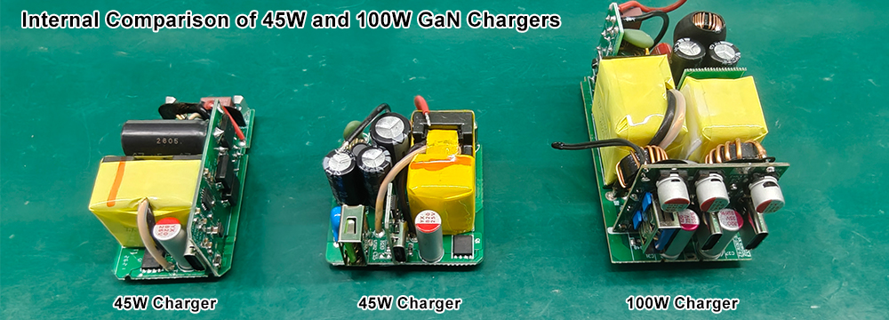
A transformer optimized for a compact 35W charger is unlikely to perform well inside a 100W multi-port GaN charger.
Each project has unique requirements.
Engineers must consider:
• Target output power.
• Switching frequency.
• PCB dimensions.
• Thermal constraints.
• Safety spacing.
• Efficiency targets.
• Certification requirements.
• Manufacturing cost.
For this reason, transformer design is closely integrated with the overall charger architecture rather than treated as an independent component selection.
Understanding Leakage Inductance: A Small Parameter with a Big Impact
One of the most important transformer characteristics engineers evaluate is leakage inductance.
Although it is rarely mentioned outside engineering circles, leakage inductance has a direct influence on charger efficiency, switching stress and electromagnetic interference.
In an ideal transformer, all magnetic energy generated by the primary winding would be transferred perfectly to the secondary winding.
In reality, this never happens.
A small portion of the magnetic field "leaks" outside the intended magnetic path instead of coupling into the secondary winding. This phenomenon is known as leakage inductance.
Excessive leakage inductance can lead to several problems:
• Higher switching losses
• Increased voltage spikes
• Greater stress on GaN devices or MOSFETs
• More heat generation
• Stronger EMI emissions
• Lower overall efficiency
For this reason, transformer designers pay close attention to winding arrangement. Interleaved winding structures, optimized spacing and improved magnetic coupling can significantly reduce leakage inductance without increasing transformer size.
The goal is not to eliminate leakage inductance completely—that is practically impossible—but to keep it within an acceptable engineering range for the chosen topology.
Why Transformer Design Directly Affects EMI Performance
Many engineers consider transformer design to be one of the largest contributors to EMI behavior.
Every switching cycle inside a charger generates rapidly changing magnetic fields.
If these fields are not properly controlled, they become unwanted electromagnetic emissions that may interfere with nearby electronic devices.
A well-designed transformer helps reduce EMI by:
• Improving magnetic coupling
• Reducing stray magnetic fields
• Minimizing parasitic capacitance
• Controlling common-mode noise
• Optimizing winding symmetry
However, transformer optimization alone is not enough.
It must work together with PCB layout, EMI filters, shielding techniques and grounding strategy.
This is why EMC testing often becomes a collaborative effort involving transformer engineers, hardware designers and PCB layout engineers rather than a single specialist.
Prototype Development: Why One Transformer Is Never Enough
Unlike standardized components such as resistors or capacitors, transformers are usually developed specifically for each charger platform.
It is common for engineering teams to produce multiple transformer samples during development.
For example:
Prototype A may achieve excellent efficiency but operate slightly warmer than expected.
Prototype B may reduce temperature but introduce additional EMI.
Prototype C may improve EMI performance while increasing manufacturing complexity.
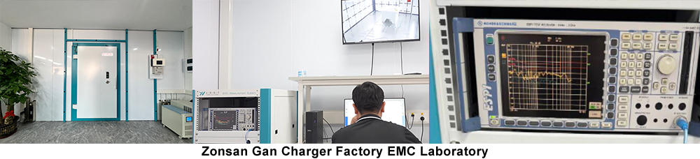
Each version is carefully evaluated through laboratory testing before the final design is selected.
This iterative process explains why transformer optimization often continues throughout the Engineering Validation Test (EVT) and Design Validation Test (DVT) stages.
Experienced manufacturers understand that investing more time during prototype development often reduces production issues after mass manufacturing begins.
Balancing Performance, Size and Manufacturability
One of the biggest engineering challenges is balancing competing design objectives.
A transformer optimized solely for maximum efficiency might become too large for a compact charger enclosure.
Reducing its size could increase operating temperature.
Using thicker copper wire may reduce resistance but complicate automated manufacturing.
Selecting a higher-grade ferrite material may improve efficiency but increase production cost.
Rather than optimizing a single parameter, engineers seek the best overall balance.
Successful transformer design is therefore a process of compromise—not perfection.
The final solution must satisfy electrical performance, thermal behavior, safety requirements, manufacturing consistency and commercial viability at the same time.
This balance is what separates mature engineering teams from simple component assemblers.
How Professional Charger Factories Validate Transformer Performance
Before a transformer design is approved for mass production, it undergoes extensive verification.
Professional charger manufacturers typically evaluate:
Electrical Performance
• Input and output characteristics
• Conversion efficiency
• Voltage regulation
• Standby power consumption
Thermal Performance
• Full-load temperature rise
• Hotspot distribution
• Long-duration operating stability
Safety Verification
• Hi-Pot (dielectric withstand) testing
• Isolation resistance
• Creepage and clearance compliance
Reliability Testing
• Continuous aging tests
• High-temperature operation
• Humidity testing
• Thermal cycling
Only after passing these evaluations is the transformer released for production.
This validation process ensures that performance measured in the engineering laboratory can be consistently reproduced during large-scale manufacturing.
Why OEM Buyers Should Care About Transformer Engineering
For many procurement teams, comparing charger quotations often begins with price, power rating and certification.
However, these specifications reveal only part of the product's quality.
The transformer is rarely listed on a quotation sheet, yet it plays a decisive role in long-term performance.
A carefully engineered transformer can help achieve:
• Higher charging efficiency
• Lower operating temperatures
• Better long-term reliability
• Reduced failure rates
• Easier EMC compliance
• More consistent mass production quality
When selecting an OEM or ODM charger manufacturer, buyers should therefore look beyond certifications and ask about the manufacturer's engineering capabilities, prototype validation process and quality control system.
These factors often determine the real value of the finished product.
Final Thoughts
The transformer may be one of the least visible components inside a charger, but it is unquestionably one of the most influential.
It is responsible not only for transferring energy safely but also for shaping efficiency, temperature, electrical noise and product reliability.
Designing a high-performance transformer requires far more than selecting a core and winding copper wire. It demands careful coordination between electrical engineering, magnetic design, PCB layout, thermal management and manufacturing expertise.
As USB-C charging power continues to increase and GaN technology enables even more compact products, transformer engineering will remain at the center of charger innovation.
For professional charger manufacturers, every successful product begins with intelligent engineering—and the transformer is one of the clearest examples of that philosophy.
Frequently Asked Questions (FAQ)
Q1: What does a transformer do inside a USB-C charger?
It transfers energy from the high-voltage primary circuit to the low-voltage secondary circuit while providing electrical isolation for user safety.
Q2: Why do GaN chargers still require transformers?
Although GaN devices improve switching efficiency, isolated AC-DC chargers still rely on high-frequency transformers for energy transfer and safety isolation.
Q3: What is leakage inductance?
Leakage inductance is magnetic energy that does not fully couple between transformer windings. Excessive leakage increases switching losses, heat and EMI.
Q4: Why are ferrite cores commonly used?
Ferrite materials offer low core losses at high switching frequencies, making them ideal for modern fast chargers.
Q5: Can transformer design affect charger temperature?
Yes. Core material, winding structure and magnetic coupling all influence heat generation and overall thermal performance.
Q6: Does every charger use the same transformer?
No. Most professional chargers use custom-designed transformers optimized for specific power levels, topologies and enclosure sizes.
Q7: How do manufacturers test transformer quality?
Through electrical testing, Hi-Pot testing, thermal evaluation, aging tests, reliability testing and production verification.
Q8: Why is transformer optimization important for OEM chargers?
It improves efficiency, reliability, manufacturing consistency and long-term product quality, reducing warranty risks for brands.
Other related reading about chargers
• How PCB Layout Determines Charger Performance: Inside the Engineering Behind Fast Chargers.↗
• How a USB-C Charger Is Designed: From Circuit Concept to Mass Production.↗
• Inside a Charger: PCB, IC and Transformer Explained.↗
• IEC 62368-1 Safety Standard.↗