Thermal Design in USB-C Chargers: How Professional Engineers Control Heat for Better Performance and Reliability
Quick Answer(Featured Snippet)
Thermal design is the engineering process of controlling how heat is generated, transferred and dissipated inside a charger. Good thermal design improves charging efficiency, extends component lifespan, enhances reliability and helps USB-C and GaN chargers meet international safety requirements. Professional charger manufacturers optimize thermal performance through PCB layout, transformer design, component placement, enclosure structure and extensive thermal validation testing.
Key Takeaways
• Every fast charger generates heat during normal operation.
• Heat itself is not the problem—poor thermal management is.
• Thermal performance begins during circuit design, not after production.
• PCB layout, transformer design, power topology and enclosure structure all influence operating temperature.
• Professional manufacturers validate thermal performance long before mass production.
Introduction
If you've ever picked up a fast charger after powering a laptop or tablet for an hour, you've probably noticed that it feels warm.
Sometimes it's only slightly above room temperature.
Sometimes it's noticeably hot.
This often leads people to ask a simple question:
"Is my charger overheating?"
In many cases, the answer is no.
Generating heat is a completely normal part of power conversion.
No electronic power supply converts electricity with 100% efficiency.
Whenever electrical energy is converted from one form to another, a small portion is inevitably lost as heat.
For engineers, however, the important question is not whether heat exists.
It is where the heat comes from, how it moves through the charger, and whether it remains within safe operating limits.
These questions form the foundation of thermal design.
Contrary to popular belief, thermal engineering isn't simply about making a charger feel cooler.
Its primary objective is ensuring that every internal component operates within its designed temperature range throughout years of continuous use.
This affects far more than user comfort.
It influences efficiency, reliability, safety, certification success and ultimately the lifespan of the entire product.
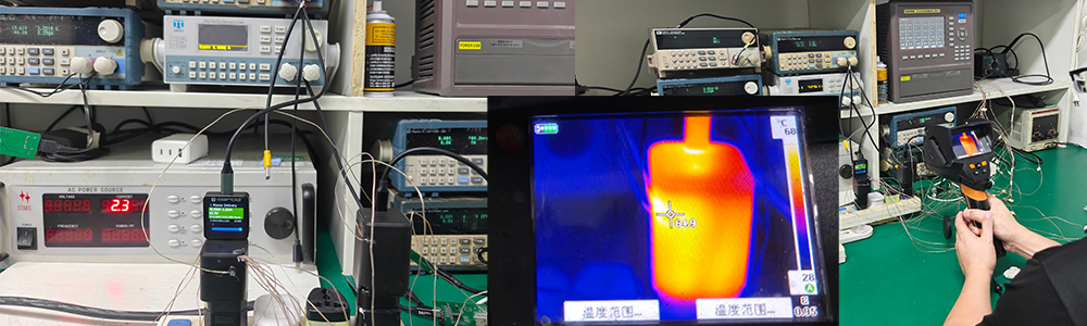
Heat Is an Engineering Challenge, Not a Manufacturing Defect
One of the biggest misconceptions surrounding chargers is the belief that a warm charger automatically indicates poor quality.
Professional engineers view the situation quite differently.
Every switching power supply generates heat.
The real engineering challenge is controlling how much heat is produced and how efficiently that heat is removed.
Consider two chargers delivering the same 100W output.
Both comply with USB Power Delivery standards.
Both pass safety certification.
Yet one consistently operates 8–10°C cooler than the other.
The difference often isn't the charging protocol or even the GaN transistor itself.
Instead, it reflects hundreds of engineering decisions made throughout product development.
Thermal performance is the result of system optimization—not a single component upgrade.
Where Does Heat Come From Inside a Charger?
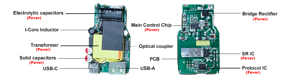
Heat inside a charger originates from several different sources.
Understanding these sources helps explain why thermal engineering involves the entire power conversion system rather than focusing on only one component.
Switching Devices
Every time a MOSFET or GaN transistor switches on and off, a small amount of energy is lost.
At switching frequencies reaching hundreds of kilohertz, these tiny losses accumulate rapidly.
Modern GaN devices significantly reduce switching loss compared with traditional silicon, but they do not eliminate heat generation completely.
Transformer
As discussed in our previous article on transformer engineering, magnetic components generate heat through:
• Copper loss
• Core loss
• Leakage flux
Transformer temperature often influences the thermal behavior of surrounding components because it is typically positioned near the center of the PCB.
Output Rectification Stage
Whether using synchronous rectification or Schottky diodes, the output stage also dissipates heat while converting transformer energy into stable DC power.
Higher output currents naturally increase these losses.
Passive Components
Capacitors, inductors and current-sensing resistors also contribute small amounts of heat.
Individually, these contributions appear insignificant.
Together, they influence the overall thermal balance inside a compact enclosure.
Heat Doesn't Stay Where It's Generated
One of the most important concepts in thermal engineering is that heat moves.
The hottest component isn't always the one generating the most energy.
Heat naturally travels through:
• Copper layers on the PCB
• Component leads
• Transformer structures
• Thermal interface materials
• Plastic enclosure
• Surrounding air
This movement creates thermal interactions between components.
For example, a transformer operating at elevated temperature may increase the temperature of nearby electrolytic capacitors.
Since capacitor lifespan decreases significantly as operating temperature rises, a seemingly minor layout decision can have long-term reliability consequences.
This illustrates why thermal engineering extends far beyond measuring individual component temperatures.
Engineers evaluate the entire thermal system.
Why Component Placement Matters
During PCB layout, engineers don't simply arrange components wherever space is available.
Thermal considerations influence placement from the earliest design stages.
High-power components are often positioned to:
• Improve airflow.
• Increase heat spreading.
• Reduce thermal interaction.
• Simplify enclosure cooling.
• Protect temperature-sensitive devices.
Sometimes relocating a transformer by only a few millimeters produces measurable improvements in thermal distribution.
Likewise, increasing copper area beneath a power device can lower junction temperature without changing the enclosure at all.
These improvements may appear small individually.
Combined across the entire design, they significantly improve long-term performance.
Thermal Design Begins Before the First Prototype Exists
Many people imagine thermal testing begins after engineers assemble the first prototype.
In reality, thermal planning starts much earlier.
Long before production samples exist, hardware engineers already estimate:
• Expected power losses.
• Component junction temperatures.
• Transformer operating conditions.
• Heat distribution across the PCB.
• Enclosure temperature rise.
These early calculations guide decisions regarding:
• PCB copper thickness.
• Component spacing.
• Enclosure dimensions.
• Transformer selection.
• Power topology.
• Ventilation strategy.
By considering thermal behavior during design rather than after testing, engineers reduce costly redesigns later in the project.
Every Engineering Decision Influences Temperature
One reason thermal engineering is so challenging is that nearly every subsystem interacts with it.
For example:
• A better PCB layout reduces electrical resistance and lowers heat generation.
• An optimized transformer decreases magnetic losses.
• Improved EMI design reduces unnecessary switching noise and associated losses.
• A more efficient flyback converter generates less waste heat.
• Better component selection reduces conduction and switching losses.
This interconnected nature explains why thermal performance cannot be improved through a single modification.
Successful charger design always approaches heat management as part of the entire engineering system rather than treating it as an isolated problem.
Why Electrolytic Capacitors Are Often the First Components Affected by Heat
Among all the components inside a charger, electrolytic capacitors deserve special attention when discussing thermal design.
Unlike ceramic capacitors or magnetic components, electrolytic capacitors contain electrolyte that gradually ages over time. Temperature is one of the biggest factors influencing this aging process.
A commonly referenced engineering guideline is that for many electrolytic capacitors, every 10°C reduction in operating temperature can significantly extend expected service life. The exact improvement depends on the capacitor's design and specifications, but the relationship between temperature and lifespan is well established.
This is one reason experienced engineers rarely evaluate only the hottest component on the PCB.
Instead, they ask another important question:
"How much heat is reaching nearby temperature-sensitive components?"
For example, if a transformer operates close to an electrolytic capacitor, the capacitor may experience a much higher temperature than expected—even if it generates very little heat itself.
Good PCB layout, thoughtful component spacing and proper airflow all help reduce this thermal interaction.
Ultimately, extending charger lifespan is often less about reducing the highest hotspot and more about protecting components that are most sensitive to long-term heat exposure.
Thermal Interface Materials: Helping Heat Move More Efficiently
Once heat is generated, engineers must decide how it will leave the charger.
Air is actually a poor conductor of heat.
Even small air gaps between components and the enclosure can reduce cooling efficiency.
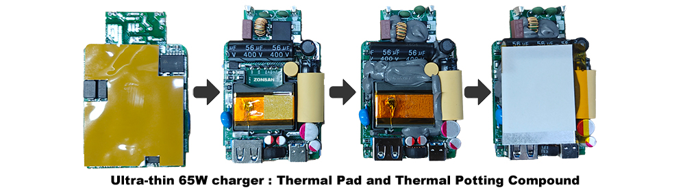
To solve this problem, many chargers use Thermal Interface Materials (TIMs).
Depending on the product design, these materials may include:
• Thermal pads
• Thermal gel
• Thermal silicone
• Thermally conductive adhesive
Their purpose is not to create cooling.
Instead, they improve heat transfer by filling microscopic air gaps between surfaces.
For example, a thermal pad placed between a transformer and the enclosure allows heat to spread more efficiently into the outer housing instead of remaining concentrated around the magnetic component.
Selecting the correct material involves balancing:
• Thermal conductivity
• Electrical insulation
• Mechanical stability
• Long-term reliability
• Manufacturing consistency
For compact GaN chargers with high power density, thermal interface materials have become increasingly important because available cooling space continues to shrink.
Why Thermal Imaging Is an Essential Engineering Tool
During charger development, engineers don't rely solely on touch to judge operating temperature.
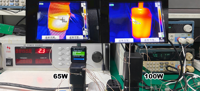
Professional laboratories commonly use infrared thermal imaging cameras to visualize how heat is distributed across the entire product.
Unlike a single temperature probe, thermal imaging provides a complete picture.
Engineers can immediately identify:
• Localized hotspots
• Uneven heat distribution
• Unexpected heating around sensitive components
• Thermal interaction between adjacent devices
More importantly, thermal images allow engineers to compare different prototype revisions.
For example, after modifying PCB copper area or adjusting transformer placement, a new thermal image can reveal whether the change actually improved heat distribution.
In many development projects, thermal imaging is repeated multiple times before the design is finalized.
Thermal Validation Before Mass Production
Achieving acceptable temperatures during laboratory testing is only the beginning.
Professional charger manufacturers also verify thermal performance under a wide range of operating conditions.
Typical evaluations include:
Full-Load Continuous Operation
Chargers are operated at rated output power for extended periods to confirm stable temperatures and consistent performance.
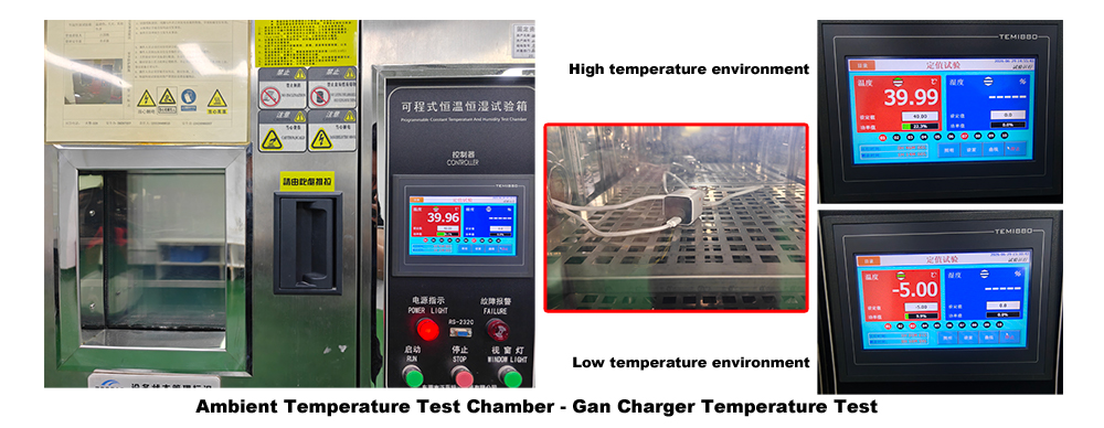
High Ambient Temperature Testing
Products are tested in elevated environmental temperatures to simulate demanding real-world conditions.
This helps verify that internal components remain within their specified operating limits even during summer use or in poorly ventilated spaces.
Thermal Cycling
Repeated heating and cooling cycles evaluate how materials expand and contract over time.
These tests help identify potential reliability issues such as solder fatigue, material deformation or weakened thermal interfaces.
Long-Duration Aging Tests
Chargers operate continuously for many hours or even days while engineers monitor electrical performance and temperature stability.
This process helps confirm that heat-related degradation does not appear during extended operation.
Common Thermal Design Mistakes
Even experienced engineering teams occasionally encounter thermal challenges during product development.
Several issues appear repeatedly across the industry.
Treating Thermal Design as a Final Step
One of the most common mistakes is postponing thermal optimization until prototype testing.
By this stage, PCB dimensions, enclosure tooling and component placement may already be fixed, making improvements more difficult and costly.
Focusing Only on the Hottest Component
Reducing the peak temperature of one device does not necessarily improve overall reliability.
Thermal interaction between neighboring components often has a greater long-term impact.
Ignoring Manufacturing Variation
A prototype assembled by experienced engineers may perform well.
However, thermal performance must remain consistent across thousands of production units.
Professional manufacturers therefore validate not only engineering samples but also mass-production processes.
Choosing Components Without Considering Heat
Electrical specifications alone do not guarantee reliable operation.
Component placement, package type and thermal resistance all influence real-world performance.
Selecting parts without considering these factors can create unnecessary thermal challenges later in development.
How Professional Charger Manufacturers Optimize Thermal Performance
Successful thermal engineering is not the result of a single breakthrough.
It is the outcome of hundreds of coordinated engineering decisions.
Professional charger manufacturers typically optimize thermal performance through:
• High-efficiency power conversion topology
• Optimized transformer design
• Careful PCB copper distribution
• Intelligent component placement
• Appropriate thermal interface materials
• Well-designed enclosure structure
• Comprehensive laboratory validation
• Continuous production quality monitoring
Rather than relying on oversized heatsinks or excessive safety margins, experienced engineers reduce heat generation at its source while ensuring efficient heat transfer throughout the product.
This system-level approach enables compact USB-C chargers to deliver increasingly higher power without compromising reliability.
Final Thoughts
Heat is an unavoidable consequence of converting electrical energy.
The objective of thermal engineering is not to eliminate heat but to control it intelligently.
Every decision—from PCB layout and transformer optimization to flyback topology, component placement and enclosure design—contributes to the final thermal behavior of a charger.
As USB-C charging power continues to increase and GaN technology enables even smaller products, thermal design becomes one of the defining factors separating a well-engineered charger from an average one.
For OEM and ODM customers, evaluating a manufacturer's thermal engineering capability provides valuable insight into its overall product development maturity.
A charger that remains reliable after years of daily use is rarely the result of chance.
It is usually the result of careful thermal engineering performed long before the product reaches the production line.
Read More

Read More
Frequently Asked Questions (FAQ)
Q1: Why do USB-C chargers become warm during use?
Because no power conversion process is 100% efficient. A small portion of electrical energy is always converted into heat.
Q2: Does a warm charger mean it is unsafe?
Not necessarily. Mild to moderate warmth is normal during operation. What matters is whether the charger stays within its designed operating temperature and complies with safety standards.
Q3: Which components generate the most heat inside a charger?
The primary heat sources are usually the switching devices (GaN transistors or MOSFETs), transformer and output rectification stage.
Q4: What is thermal design?
Thermal design is the engineering process of controlling heat generation, transfer and dissipation to improve efficiency, reliability and product lifespan.
Q5: Why are electrolytic capacitors sensitive to heat?
Higher operating temperatures accelerate aging of the electrolyte, reducing the component's expected service life.
Q6: What are thermal interface materials?
They are materials such as thermal pads or thermal gel that improve heat transfer between components and the enclosure by reducing air gaps.
Q7: How do manufacturers test charger temperatures?
Professional manufacturers use infrared thermal imaging, temperature sensors, full-load operation, thermal cycling and environmental chamber testing.
Q8: Why is thermal engineering important for OEM charger buyers?
Strong thermal engineering improves efficiency, reliability, certification success and long-term product consistency, helping reduce warranty claims and customer complaints.
Other related reading
• How Flyback Converters Work in USB-C Chargers: The Power Conversion Technology Behind Fast Charging.↗
• How Transformer Design Determines Charger Efficiency: The Engineering Behind Every Fast Charger.↗
• How PCB Layout Determines Charger Performance: Inside the Engineering Behind Fast Chargers.↗
• How EMI Affects Charger Performance: Engineering Stable, Safe and Compliant USB-C Chargers.↗
• JEDEC Thermal Standards and Publications.↗