Thermal Reliability Engineering for GaN Chargers: How Charger Factory Manufacturers Control Heat in High-Power Charging Products
Thermal reliability in GaN charger manufacturing is the process of controlling and validating heat generated during power conversion to ensure stable, safe and reliable long-term operation. Professional charger manufacturers evaluate temperature rise, internal hot spots, high-load operation, thermal materials, PCB layout and enclosure design, especially for compact 100W, 140W and higher-power USB-C chargers. Thermal performance must also remain consistent during mass production, not just in engineering prototypes.
Key Takeaways
• Higher power creates greater thermal challenges. Compact 65W, 100W, 140W and higher-power chargers require careful thermal engineering.
• GaN does not eliminate heat. GaN technology can improve efficiency and power density, but heat is still generated during power conversion.
• Thermal design is a system. Component selection, PCB layout, transformer design, thermal materials and enclosure structure all affect temperature performance.
• Hot spots matter. Engineers need to monitor critical internal components, not only the temperature of the external charger housing.
• Testing must cover realistic conditions. High-load, long-duration, multi-port and different ambient-temperature conditions can reveal thermal problems that short functional tests may miss.
• Manufacturing consistency is critical. Thermal pad placement, component variation and assembly accuracy can affect the thermal performance of mass-produced chargers.
• Thermal reliability supports long-term product reliability. Proper heat management can help reduce thermal stress and support stable charger performance over time.
• Thermal engineering connects with the wider quality system. PFMEA, Control Plans, SPC, Traceability, Reliability Testing and CAPA work together to control and continuously improve charger quality.
Why Thermal Management Matters for Compact GaN and USB-C PD Chargers
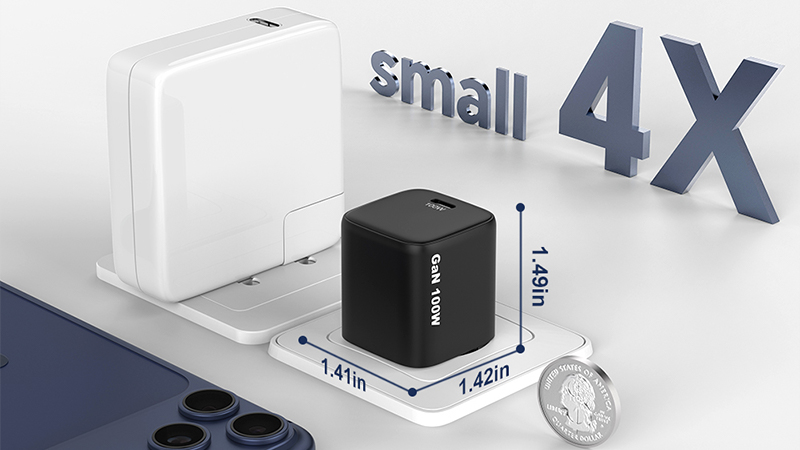
Although the charger is small, the engineering design inside it is by no means simple.
In fact, as charger power increases and product sizes become smaller, thermal management becomes one of the more important challenges for manufacturers.
The thermal characteristics of a 20W charger differ significantly from those of a 100W GaN charger, while a 140W USB-C PD charger imposes even higher levels of thermal and electrical stress.
The basic question is simple: Where does the heat go?
But finding the right answer can involve many parts of the product:
• GaN power devices.
• Transformer design.
• PCB layout.
• Power conversion efficiency.
• Thermal materials.
• Internal spacing.
• Charger enclosure.
• Component selection.
• Operating conditions.
For consumers, thermal performance is usually noticed as a simple feeling: "The charger feels hot."
For engineers, it is much more complicated.
They need to understand the magnitude and location of heat generation, the heat conduction paths within the product, and whether the temperature remains within an acceptable range during long-term operation.
Consequently, thermal reliability engineering has become increasingly important in the manufacturing of modern GaN chargers.
What Is Thermal Reliability in Charger Factory Manufacturing?
Thermal reliability refers to the ability of a charger to maintain stable and safe operation when exposed to the temperatures and thermal stresses expected during its intended use.
It is not simply about making a charger "cool." Chargers do not need to remain cool while operating; certain components naturally generate heat during the process of converting electrical energy.
The engineering goal is to make sure that:
• Heat generation is controlled.
• Heat is distributed properly.
• Critical components remain within appropriate operating conditions.
• The enclosure does not create unacceptable temperature conditions.
• Performance remains stable during prolonged use.
In other words: Good thermal design is about controlling heat, not eliminating heat completely.
Why Higher Charger Power Creates More Thermal Challenges
The process of electrical energy conversion can never achieve perfect efficiency; inevitably, some energy is converted into heat. As charger power increases, the amount of heat that needs to be dissipated often rises accordingly.
Consider the difference between a small low-power charger and a high-power charger.
A 20W charger may have relatively modest heat generation.
A 100W charger operates at a much higher power level.
A 140W charger can place even greater demands on:
• Power components.
• Magnetic components.
• PCB traces.
• Thermal paths.
• Enclosure design.
At the same time, customers often want the opposite of what engineers might prefer.
They want the charger to become:
• Smaller. Lighter. More powerful. Faster.
This creates the central challenge of modern charger design: Higher power density with controlled thermal performance.
Why GaN Chargers Need Careful Thermal Engineering
GaN, or gallium nitride, has become an important technology in modern fast chargers. Compared with traditional silicon-based power devices, GaN technology can enable higher switching frequencies and more compact power conversion designs.
This is one reason GaN chargers can achieve high power in relatively small packages.
But it would be wrong to assume: GaN = no heat.
GaN devices still generate heat.
The overall thermal performance of a charger depends on the entire power system.
For example:
• GaN power devices. Transformer. Rectification components. Capacitors. Controller ICs. PCB. Mechanical structure.
All contribute to the final thermal behavior.
So when engineers develop a compact 65W, 100W or 140W GaN charger, they cannot look at the GaN component alone. They need to evaluate the complete system.
Although the charger is small, the engineering design inside it is by no means simple.
In fact, as charger power increases and product sizes become smaller, thermal management becomes one of the more important challenges for manufacturers.
The thermal characteristics of a 20W charger differ significantly from those of a 100W GaN charger, while a 140W USB-C PD charger imposes even higher levels of thermal and electrical stress.
The basic question is simple: Where does the heat go?
But finding the right answer can involve many parts of the product:
• GaN power devices.
• Transformer design.
• PCB layout.
• Power conversion efficiency.
• Thermal materials.
• Internal spacing.
• Charger enclosure.
• Component selection.
• Operating conditions.
For consumers, thermal performance is usually noticed as a simple feeling: "The charger feels hot."
For engineers, it is much more complicated.
They need to understand the magnitude and location of heat generation, the heat conduction paths within the product, and whether the temperature remains within an acceptable range during long-term operation.
Consequently, thermal reliability engineering has become increasingly important in the manufacturing of modern GaN chargers.
What Is Thermal Reliability in Charger Factory Manufacturing?
Thermal reliability refers to the ability of a charger to maintain stable and safe operation when exposed to the temperatures and thermal stresses expected during its intended use.
It is not simply about making a charger "cool." Chargers do not need to remain cool while operating; certain components naturally generate heat during the process of converting electrical energy.
The engineering goal is to make sure that:
• Heat generation is controlled.
• Heat is distributed properly.
• Critical components remain within appropriate operating conditions.
• The enclosure does not create unacceptable temperature conditions.
• Performance remains stable during prolonged use.
In other words: Good thermal design is about controlling heat, not eliminating heat completely.
Why Higher Charger Power Creates More Thermal Challenges
The process of electrical energy conversion can never achieve perfect efficiency; inevitably, some energy is converted into heat. As charger power increases, the amount of heat that needs to be dissipated often rises accordingly.
Consider the difference between a small low-power charger and a high-power charger.
A 20W charger may have relatively modest heat generation.
A 100W charger operates at a much higher power level.
A 140W charger can place even greater demands on:
• Power components.
• Magnetic components.
• PCB traces.
• Thermal paths.
• Enclosure design.
At the same time, customers often want the opposite of what engineers might prefer.
They want the charger to become:
• Smaller. Lighter. More powerful. Faster.
This creates the central challenge of modern charger design: Higher power density with controlled thermal performance.
Why GaN Chargers Need Careful Thermal Engineering
GaN, or gallium nitride, has become an important technology in modern fast chargers. Compared with traditional silicon-based power devices, GaN technology can enable higher switching frequencies and more compact power conversion designs.
This is one reason GaN chargers can achieve high power in relatively small packages.
But it would be wrong to assume: GaN = no heat.
GaN devices still generate heat.
The overall thermal performance of a charger depends on the entire power system.
For example:
• GaN power devices. Transformer. Rectification components. Capacitors. Controller ICs. PCB. Mechanical structure.
All contribute to the final thermal behavior.
So when engineers develop a compact 65W, 100W or 140W GaN charger, they cannot look at the GaN component alone. They need to evaluate the complete system.
Where Does Heat Come From Inside a Charger?
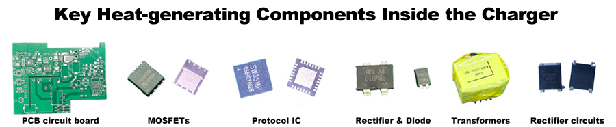
Understanding heat generation is the first step in thermal engineering. Several areas inside a charger can contribute to temperature rise.
1. Power Switching Components
Power switching devices handle high-frequency electrical conversion.
During operation, losses occur.
Even when the efficiency is high, some energy becomes heat.
The actual thermal performance depends on factors such as:
Switching frequency.
• Load level.
• Device characteristics.
• Circuit topology.
• Operating temperature.
For high-power GaN chargers, these components are particularly important during thermal analysis.
2. Transformer and Magnetic Components
The transformer is another important heat source in many charger designs. Losses can come from:
• Copper resistance.
• Core losses.
• Switching conditions.
• Operating frequency.
Transformer design therefore has a direct influence on the thermal behavior of the charger. An efficient power design needs to consider both electrical performance and heat generation.
3. Rectification and Power Management Components
Other components in the power conversion system also generate losses. Examples include:
• Rectifiers.
• MOSFETs.
• Controller ICs.
• Protection components.
Each individual loss may seem small. But when several heat sources operate inside a compact enclosure, their combined effect becomes important.
4. Capacitors and Supporting Components
Capacitors and other passive components can also experience temperature increases. Temperature is particularly important because component lifetime can be affected by operating conditions.
For this reason, engineers consider the thermal environment around critical components rather than looking only at the maximum external housing temperature.
5. PCB and Connection Losses
PCB traces, connectors and solder connections also contribute to electrical losses. When current increases, resistance-related losses become more important. This is one reason PCB layout matters so much in high-power charger design.
The PCB is not simply a platform for mounting components.
It is part of the electrical and thermal system.
How Charger Manufacturers Measure Temperature
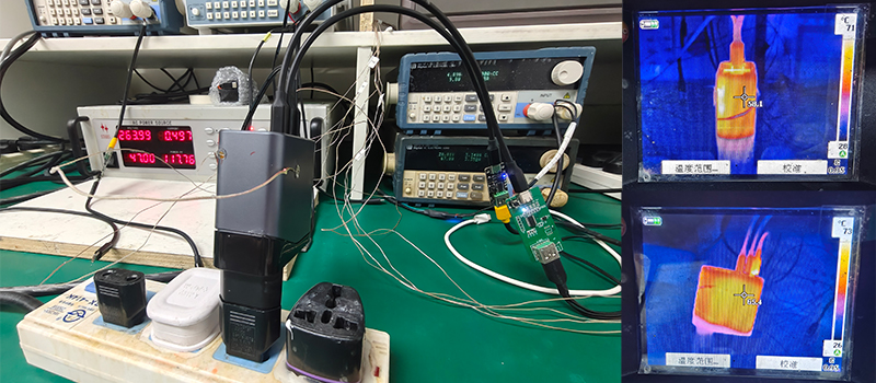
Thermal engineering requires actual data. Engineers cannot reliably assess a charger's thermal performance simply by touching its casing.
Different measurement methods can be used during product development and reliability testing.
Thermocouples
Thermocouples are commonly used for temperature measurement. Engineers can place sensors at specific points to monitor:
• Component temperature.
• PCB temperature.
• Transformer temperature.
• Internal housing temperature.
This allows engineers to see how temperature changes during operation.
Infrared Thermal Imaging
Thermal cameras can provide a visual representation of temperature distribution. Instead of measuring only one point, engineers can observe the overall thermal pattern.
This can help identify:
• Hot spots.
• Uneven heat distribution.
• Unexpected heating areas.
• Areas requiring design improvement.
A thermal image can sometimes reveal a problem that would not be obvious from a single temperature measurement.
Why Hot Spots Matter
One of the important concepts in thermal engineering is the hot spot. Charger enclosure may have an acceptable average temperature while one internal component operates significantly hotter than surrounding components.
That component may become the limiting factor for long-term reliability.
For example:
A 100W charger may have several heat-generating components. If one component has poor thermal dissipation, its local temperature can rise much faster than the rest of the system.
Therefore, thermal engineers will simultaneously focus on: Overall temperature and Local temperature distribution.
Thermal Design Starts With the PCB
Many people believe that thermal management begins with the charger housing, but in reality, the process starts much earlier—during the initial design phase—as PCB design significantly impacts heat distribution.
Engineers may consider:
• Component placement.
• Copper area.
• PCB layer structure.
• Current paths.
• Distance between heat-generating components.
• Thermal vias.
The basic idea is straightforward: Do not allow multiple major heat sources to create an unnecessarily concentrated thermal area. Good layout can make later thermal management much easier.
Component Placement and Thermal Distribution
Component placement is particularly important in compact chargers.
If several high-loss components are positioned too close together, their heat can accumulate.
This can create a local hot zone. Engineers therefore need to consider:
• Which components generate heat.
• How much heat they generate.
• Where that heat can move.
• Whether nearby components are temperature-sensitive.
A compact design is not merely about cramming more components into a limited space; the key lies in the ingenious layout and arrangement of those components.
Thermal Interface Materials
Thermal interface materials can help transfer heat between components and other heat-spreading structures. Depending on the design, manufacturers may use:
• Thermal pads.
• Thermal films.
• Thermal compounds.
• Other heat-transfer materials.
However, adding thermal material does not automatically solve a thermal problem.
The material's thickness, position, degree of compression, and contact area all affect the final heat dissipation performance.
Therefore, the application of thermal interface materials often needs to be integrated into controlled manufacturing processes.
Factory Manufacturing Accuracy Matters to Thermal Performance
This is an important point for OEM customers. A good thermal design on paper does not guarantee identical thermal performance in mass production.
Consider a thermal pad. If it is:
• Misaligned.
• Incorrectly positioned.
• Too thick.
• Too thin.
the actual heat-transfer path may change. The same applies to other assembly details.
This is why thermal reliability is connected with the broader manufacturing quality system.
A thermal design needs to be reproduced consistently on the production line.
Thermal Performance and Charger Enclosure Design
The casing is also part of the thermal management system; for compact chargers, engineers need to strike a balance among the following aspects:
• Product size.
• Safety requirements.
• Mechanical strength.
• Heat dissipation.
• User comfort.
A smaller enclosure provides less internal space for heat distribution. But increasing the enclosure size may reduce the product's portability.
This is one reason high-power charger design requires trade-offs. There is no single solution that works for every product.
Why Charger Size and Thermal Performance Are Connected
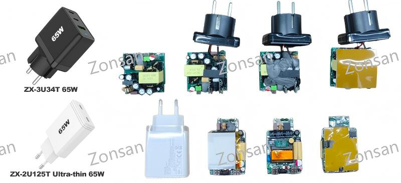
The relationship is fairly straightforward. When a charger becomes smaller while maintaining similar power output, its power density increases. Higher power density generally means engineers have less physical space to distribute heat.
For example:
A 65W charger in a relatively large housing has more internal volume than a 65W charger designed to be ultra-thin.
The electrical power is the same.
But the thermal engineering challenge is different.
This is especially relevant to ultra-slim and compact GaN charger products.
Thermal Testing Under Different Loads
Testing a charger at only one load condition does not provide a complete picture. Engineers may evaluate thermal performance under:
• Light load.
• Medium load.
• High load.
• Maximum rated load.
The temperature response can be different at each level.
At low load, heat generation may be relatively low. As load increases, losses and temperature rise can increase.
For high-power chargers, maximum-load testing is particularly important. But real-world usage should also be considered.
A customer may not always use the charger at exactly its maximum rated output. Therefore, engineers can evaluate several operating points to understand the broader thermal behavior.
Thermal Testing for Multi-Port Chargers
Multi-port chargers add another challenge.
A charger with: 2 USB-C ports and 1 USB-A port. may have different thermal behavior depending on which ports are active.
For example:
Scenario 1: USB-C1 only.
Scenario 2: USB-C2 only.
Scenario 3: USB-C1 + USB-C2.
Scenario 4: USB-C1 + USB-A.
Scenario 5: All ports operating simultaneously.
The internal power distribution changes between these conditions. Thermal testing should consider realistic port combinations rather than testing only one output configuration.

Read More
How Thermal Management Affects Long-Term Reliability
Temperature is not only a comfort issue. Long-term exposure to elevated temperatures can influence component aging. Different electronic components have different temperature sensitivities.
For a charger manufacturer, this means thermal design can influence:
• Component lifetime.
• Electrical stability.
• Material aging.
• Long-term reliability.
This is why thermal testing belongs inside a broader reliability engineering program. A charger that operates efficiently and maintains controlled temperatures has a stronger foundation for long-term reliability.
Thermal Design Is a System, Not a Single Component
One of the most common misunderstandings is focusing on a single component.
For example:
"GaN runs cooler." That statement is too simple.
The final temperature of a charger depends on the entire system: Power architecture
• Component selection
• PCB layout
• Transformer design
• Thermal materials
• Mechanical structure
• Firmware/control strategy
• Manufacturing consistency
All of these factors can influence thermal performance.
This is why professional charger development requires cooperation between:
• Electrical engineers.
• Mechanical engineers.
• PCB engineers.
• Reliability engineers.
• Manufacturing engineers.
Thermal Reliability During Mass Production
Thermal performance should not be checked only during product development. After a charger enters mass production, manufacturing variation still needs to be controlled. This is where the previous ZEEAS quality systems become relevant.
For example:
PFMEA —— can identify thermal-related production risks.
Control Plan —— can define critical thermal assembly controls.
Traceability —— can identify which production batches are involved if a thermal issue appears.
CAPA —— can be used when a repeated thermal problem requires corrective and preventive action.
This creates a complete chain: Thermal Design → Manufacturing Control → Thermal Testing → Traceability → Continuous Improvement
• Learn here: “Traceability System in Electronics Manufacturing: How Charger Factories Track Every Production Step.” And “Statistical Process Control (SPC) in Charger Manufacturing: How Data Helps Prevent Quality Problems.”
What Happens When Thermal Testing Reveals a Problem?
Finding a thermal problem during development is not necessarily bad news. In fact, it is often much better to find the problem before mass production.
Engineers may investigate:
• Is the heat source larger than expected?
• Is component efficiency lower than expected?
• Is the PCB layout creating excessive concentration?
• Is the thermal interface working correctly?
• Is the enclosure restricting heat distribution?
Depending on the result, the design may be changed.
Possible improvements include:
• Component replacement.
• PCB layout adjustment.
• Thermal material optimization.
• Transformer redesign.
• Power control adjustment.
• Mechanical structure changes.
The product can then be tested again.
This is how reliability engineering works in practice: the core lies not in assuming the initial design is perfect, but in testing, learning from experience, and making continuous improvements.
Thermal Reliability Testing Before Mass Production
Thermal design needs to be verified under real operating conditions. Although simulation helps engineers understand how heat is conducted within a product, physical testing remains essential. During engineering validation, manufacturers may test chargers under different combinations of:
Input voltage.
• Output power.
• Ambient temperature.
• Charging duration.
• Port combinations.
The objective is to understand not only the highest temperature, but also how quickly the temperature rises and whether it eventually reaches a stable condition. A charger that reaches a stable temperature after several minutes behaves differently from one that continues heating throughout a long test.
That difference matters when evaluating long-term reliability.
• You can read "Reliability Testing for USB-C Chargers: How Manufacturers Verify Long-Term Performance" here.
How Engineers Evaluate Temperature Rise
Temperature rise is normally evaluated relative to the surrounding environment.
For example, if the ambient temperature is 25°C and a specific internal component reaches 75°C, the temperature rise is approximately 50°C.
Engineers may compare this information with:
• Component specifications.
• Design limits.
• Safety requirements.
• Customer requirements.
• Internal reliability targets.
It is also useful to compare different production samples. If one sample operates significantly hotter than others under the same conditions, engineers may investigate whether there is:
• Component variation.
• Assembly variation.
• PCB variation.
• Testing variation.
This is where thermal testing becomes connected with manufacturing quality control.
Thermal Derating in High-Power Chargers
Another important concept in high-power charger design is thermal derating. In simple terms, derating means reducing the operating output or changing the operating behavior when temperature or other conditions become more demanding.
For example, a charger may provide its full rated power under normal conditions but reduce output under a particularly high thermal load. This can help keep critical components within their designed operating range.
Thermal behavior therefore needs to be considered together with:
• Power allocation.
• Protection logic.
• Firmware or control strategy.
• Component temperature.
• Ambient conditions.
This becomes particularly important for compact, high-power USB-C PD chargers. USB-IF USB Power Delivery Overview.↗
Why 140W and 240W Chargers Need More Thermal Attention
As charger power increases, thermal engineering becomes increasingly demanding.A 20W charger and a 240W charger cannot simply be treated as the same design at different power levels.
Higher-power products may require closer attention to:
• Power component losses.
• Transformer design.
• PCB current paths.
• Heat distribution.
• Component spacing.
• Thermal interface materials.
• Enclosure design.
There is also another challenge: High-power chargers are often expected to remain relatively compact.
That means engineers are solving two problems at the same time:
More power
while
Maintaining a manageable thermal environment.
This is one reason high-power GaN charger development requires considerable engineering work rather than simply selecting higher-rated components.

Common Thermal Design Mistakes
Mistake 1: Looking Only at the External Housing Temperature
A charger may not feel extremely hot on the outside while an internal component is operating at a much higher temperature. Engineers therefore need to understand internal hot spots rather than relying only on the surface temperature.
Mistake 2: Testing Only at Low Power
A charger that performs well at 30% load does not necessarily behave the same way at maximum rated power. High-load and sustained-load testing provide much more useful information for high-power products.
Mistake 3: Ignoring Production Variation
A thermal design may work perfectly in an engineering prototype, but if a thermal pad, component or assembly position varies during mass production, the final thermal performance can change.
This is why thermal-related manufacturing steps should be controlled.
Mistake 4: Solving Heat Problems Too Late
Thermal problems are much easier to address during the design stage. Once the enclosure, PCB and components have been finalized, major thermal changes can become more expensive and time-consuming.
Good thermal engineering starts early.
How OEM Buyers Should Evaluate a Charger Factory's Thermal Engineering Capability
For an OEM buyer, it can be difficult to judge a manufacturer's engineering capability simply by looking at a finished charger. A better approach is to ask how the factory validates thermal performance.
Useful questions include:
1. How is temperature measured during product development?
2. Does the factory perform long-duration load testing?
3. How are thermal hot spots identified?
4. Are different load conditions tested?
5. Are multi-port combinations evaluated?
6. How are thermal failures investigated?
7. Are thermal-related production risks included in the quality control system?
The answers can reveal whether thermal engineering is actually part of the manufacturer's development process or whether the factory relies mainly on final inspection.
Thermal Engineering and the Future of GaN Chargers
The charger market continues moving toward:
• Higher power density.
• Smaller form factors.
• More USB-C ports.
• Faster charging.
• More intelligent power management.
These trends make thermal engineering even more important.
GaN technology will continue to play a major role in this development, but GaN alone does not solve every thermal challenge. The next generation of charger products will depend on the combination of:
1. Efficient power architecture
2. Advanced semiconductor technology
3. Better PCB design
5. Improved thermal management
6. Accurate manufacturing
7. Reliable testing
This is what allows manufacturers to increase power without simply increasing product size.
Thermal Reliability as Part of a Complete Manufacturing System
Thermal performance should not be treated as an isolated engineering topic. It connects directly with the quality systems discussed throughout the ZEEAS series.
PFMEA identifies potential thermal risks.
↓
Control Plan defines how critical processes are controlled.
↓
SPC monitors process stability.
↓
Traceability records material and production history.
↓
Thermal Testing verifies actual product behavior.
↓
Failure Analysis investigates unexpected results.
↓
CAPA prevents repeated problems.
This is a much stronger approach than simply checking the temperature of finished products before shipment.
• Read next: CAPA Process in Charger Manufacturing: How Factories Prevent Repeated Quality Problems.↗
Final Thoughts
As chargers become smaller and more powerful, thermal management becomes one of the fundamental engineering challenges behind modern charging products.
A charger does not need to stay completely cool. What matters is whether heat is generated, distributed and controlled in a way that supports stable and reliable operation.
For GaN and high-power USB-C chargers, this requires attention to the entire product:
• Power architecture.
• Component selection.
• PCB layout.
• Transformer design.
• Thermal interface materials.
• Enclosure structure.
• Manufacturing consistency.
• Reliability testing.
For OEM and ODM customers, thermal engineering is therefore worth evaluating alongside certifications, price and production capacity.
A professional charger manufacturer should be able to explain not only how much power a product can deliver, but also how the product manages the heat created while delivering that power. That difference becomes increasingly important as the industry moves toward smaller 100W, 140W and even higher-power charging products.
In the end, good thermal design is not about making a charger look technically impressive. It is about making sure the charger can perform its job reliably, repeatedly and safely over the expected life of the product.
Frequently Asked Questions
Q1: Why do GaN chargers generate heat?
GaN chargers still generate heat because electrical power conversion is not 100% efficient. Some energy is converted into heat during operation.
Q2: Does GaN technology make a charger completely cool?
No. GaN can improve efficiency and enable compact designs, but the complete charger still generates heat and requires appropriate thermal management.
Q3: How do charger manufacturers measure temperature?
Engineers can use methods such as thermocouples, temperature sensors and infrared thermal imaging to measure internal and external temperatures.
Q4: Why is thermal testing important for 100W chargers?
Higher-power chargers generally have greater power density and can experience greater thermal stress, making sustained-load and thermal testing important.
Q5: Do multi-port chargers require thermal testing?
Yes. Different combinations of active ports can create different power distributions and thermal conditions.
Q6: What is a thermal hot spot?
A thermal hot spot is a localized area or component that reaches a significantly higher temperature than surrounding areas.
Q7: Can thermal problems occur during mass production?
Yes. Differences in components, assembly, thermal materials or process conditions can affect the thermal performance of production units.
Q8: How does thermal testing support charger reliability?
Thermal testing helps engineers identify excessive temperature rise, hot spots and other conditions that could affect long-term product performance.
Reviewed by: ZONSAN R&D Team — Miller and Lucas Wang
Technical Review: Charging Products & Power Solutions
Last reviewed: [August 17, 2026]
Mistake 1: Looking Only at the External Housing Temperature
A charger may not feel extremely hot on the outside while an internal component is operating at a much higher temperature. Engineers therefore need to understand internal hot spots rather than relying only on the surface temperature.
Mistake 2: Testing Only at Low Power
A charger that performs well at 30% load does not necessarily behave the same way at maximum rated power. High-load and sustained-load testing provide much more useful information for high-power products.
Mistake 3: Ignoring Production Variation
A thermal design may work perfectly in an engineering prototype, but if a thermal pad, component or assembly position varies during mass production, the final thermal performance can change.
This is why thermal-related manufacturing steps should be controlled.
Mistake 4: Solving Heat Problems Too Late
Thermal problems are much easier to address during the design stage. Once the enclosure, PCB and components have been finalized, major thermal changes can become more expensive and time-consuming.
Good thermal engineering starts early.
How OEM Buyers Should Evaluate a Charger Factory's Thermal Engineering Capability
For an OEM buyer, it can be difficult to judge a manufacturer's engineering capability simply by looking at a finished charger. A better approach is to ask how the factory validates thermal performance.
Useful questions include:
1. How is temperature measured during product development?
2. Does the factory perform long-duration load testing?
3. How are thermal hot spots identified?
4. Are different load conditions tested?
5. Are multi-port combinations evaluated?
6. How are thermal failures investigated?
7. Are thermal-related production risks included in the quality control system?
The answers can reveal whether thermal engineering is actually part of the manufacturer's development process or whether the factory relies mainly on final inspection.
Thermal Engineering and the Future of GaN Chargers
The charger market continues moving toward:
• Higher power density.
• Smaller form factors.
• More USB-C ports.
• Faster charging.
• More intelligent power management.
These trends make thermal engineering even more important.
GaN technology will continue to play a major role in this development, but GaN alone does not solve every thermal challenge. The next generation of charger products will depend on the combination of:
1. Efficient power architecture
2. Advanced semiconductor technology
3. Better PCB design
5. Improved thermal management
6. Accurate manufacturing
7. Reliable testing
This is what allows manufacturers to increase power without simply increasing product size.
Thermal Reliability as Part of a Complete Manufacturing System
Thermal performance should not be treated as an isolated engineering topic. It connects directly with the quality systems discussed throughout the ZEEAS series.
PFMEA identifies potential thermal risks.
↓
Control Plan defines how critical processes are controlled.
↓
SPC monitors process stability.
↓
Traceability records material and production history.
↓
Thermal Testing verifies actual product behavior.
↓
Failure Analysis investigates unexpected results.
↓
CAPA prevents repeated problems.
This is a much stronger approach than simply checking the temperature of finished products before shipment.
• Read next: CAPA Process in Charger Manufacturing: How Factories Prevent Repeated Quality Problems.↗
Final Thoughts
As chargers become smaller and more powerful, thermal management becomes one of the fundamental engineering challenges behind modern charging products.
A charger does not need to stay completely cool. What matters is whether heat is generated, distributed and controlled in a way that supports stable and reliable operation.
For GaN and high-power USB-C chargers, this requires attention to the entire product:
• Power architecture.
• Component selection.
• PCB layout.
• Transformer design.
• Thermal interface materials.
• Enclosure structure.
• Manufacturing consistency.
• Reliability testing.
For OEM and ODM customers, thermal engineering is therefore worth evaluating alongside certifications, price and production capacity.
A professional charger manufacturer should be able to explain not only how much power a product can deliver, but also how the product manages the heat created while delivering that power. That difference becomes increasingly important as the industry moves toward smaller 100W, 140W and even higher-power charging products.
In the end, good thermal design is not about making a charger look technically impressive. It is about making sure the charger can perform its job reliably, repeatedly and safely over the expected life of the product.
Frequently Asked Questions
Q1: Why do GaN chargers generate heat?
GaN chargers still generate heat because electrical power conversion is not 100% efficient. Some energy is converted into heat during operation.
Q2: Does GaN technology make a charger completely cool?
No. GaN can improve efficiency and enable compact designs, but the complete charger still generates heat and requires appropriate thermal management.
Q3: How do charger manufacturers measure temperature?
Engineers can use methods such as thermocouples, temperature sensors and infrared thermal imaging to measure internal and external temperatures.
Q4: Why is thermal testing important for 100W chargers?
Higher-power chargers generally have greater power density and can experience greater thermal stress, making sustained-load and thermal testing important.
Q5: Do multi-port chargers require thermal testing?
Yes. Different combinations of active ports can create different power distributions and thermal conditions.
Q6: What is a thermal hot spot?
A thermal hot spot is a localized area or component that reaches a significantly higher temperature than surrounding areas.
Q7: Can thermal problems occur during mass production?
Yes. Differences in components, assembly, thermal materials or process conditions can affect the thermal performance of production units.
Q8: How does thermal testing support charger reliability?
Thermal testing helps engineers identify excessive temperature rise, hot spots and other conditions that could affect long-term product performance.
Reviewed by: ZONSAN R&D Team — Miller and Lucas Wang
Technical Review: Charging Products & Power Solutions
Last reviewed: [August 17, 2026]