How USB-C PD Protocol Tuning Works in Charger Development
PD protocol tuning is the process of making a USB-C charger and the connected device communicate correctly about voltage, current, power and charging behavior.
It is not simply a matter of adding “PD” to a charger specification.
A custom USB-C PD charger has to recognize the connected device, advertise the right power profiles, negotiate an appropriate output and change its behavior when the load changes. For a 65W or 100W charger, this becomes even more important when several USB-C ports are used together.
Good PD charger manufacturer therefore needs to consider the protocol, power architecture, firmware or control logic, protection, thermal behavior and multi-port power allocation as one system.
What Is PD Protocol Tuning?
USB Power Delivery, commonly called USB PD, allows a charger and a compatible device to communicate before delivering higher levels of power.
That communication is one reason a modern USB-C charger can support different devices without simply pushing the maximum available wattage into everything that is connected.
For example, the same charger may be used with All Smartphone, tablet, laptop, Wireless earbuds, portable monitor, USB-C hub.
The power requirement is different for each device. A phone may only request a relatively low power level, while a laptop may request much more.
The charger has to respond accordingly. This is where PD protocol tuning comes in.
In a custom charger project, engineers need to make sure the charger advertises the correct capabilities, responds properly to the device's requests and maintains stable output throughout the charging process.
It sounds straightforward. In practice, it is one of the areas where charger engineering becomes much more than simply assembling components.
Why PD Protocol Matters in a USB-C Charger
A basic wall charger can be described relatively simply: AC input → power conversion → DC output.
A modern USB-C PD charger is more complicated. The charger needs to understand what the connected device can accept.
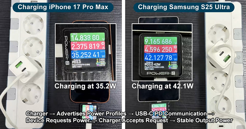
A simplified process looks like this: Charger connected → USB-C connection detected → PD communication starts → Charger advertises available power profiles → Device requests a suitable profile → Charger accepts the request → Output voltage/current changes → Charging continues under active monitoring.
The actual implementation depends on the controller, firmware and charger architecture. But the basic idea is the same: The charger and device have to agree on how much power should be delivered.
PD Negotiation Is Not the Same as “Fast Charging”
This distinction is worth making. Charger can have a high wattage rating and still provide a poor charging experience if the protocol implementation is not handled correctly.
Example: 100W charger does not mean every connected phone will receive 100W. The connected device decides what it needs within the capabilities supported by the charger and the charging system.
Laptop may request a higher voltage and power level.
Smartphone may use a lower power profile.
Another device may only use the default USB power level.
So when someone searches for a 100W USB-C PD charger, the important question is not only: “Does it say 100W?”
The better question is: “What PD profiles does it actually support, and how does it behave with the devices I need to charge?”
That is a much more useful engineering question.
What Does a USB-C PD Charger Actually Advertise?
A PD charger can advertise several supported power profiles. Depending on the charger design, these can include combinations of: 5V, 9V, 12V, 15V, 20V. Higher-power designs can support additional voltage levels under newer USB PD specifications.
The charger essentially tells the connected device: “These are the power options I can provide.”
The device then evaluates those options and requests an appropriate one. A simplified 65W charger might support: 5V/3A, 9V/3A, 12V/3A, 15V/3A, 20V/3.25A.
The exact profiles depend on the specific product.
A real ZONSAN 65W GaN model, for example, lists multiple USB-C output levels and PPS support, illustrating why the product specification needs to go beyond simply saying “65W PD charger.”
* What Is a GaN Charger?
How Does PD Protocol Tuning Work?
A charger engineer normally does not start by randomly changing voltage values. The process begins with the product requirements.
Product target: 65W USB-C PD charger
Port configuration: 1 × USB-C
Target devices: Smartphones + tablets + laptops
Required protocols: PD + PPS
Target markets: Europe / Korea / North America
From there, the engineering team needs to determine:
• Which PD profiles are required
• Which controller should be used
• What power stage is appropriate
• What components are required
• How much thermal margin is needed
• What protection functions are required
• What certification requirements apply
Only then does protocol tuning become part of the actual development process.
Step 1: Define the Target Power Profiles
Before tuning the protocol, engineers need to know what the charger is supposed to deliver.
Take a 45W charger as an example, the product may need to support: 5V, 9V, 12V, 15V, 20V, PPS or AVS.
But another 45W charger may have a different requirement. The difference may come from the target device.
Charger designed mainly for smartphones does not necessarily need the same power strategy as a charger designed for laptops. This is why a professional custom PD charger manufacturer should start with the intended application rather than selecting a generic “45W PD solution” first.
Step 2: Select the PD Controller and Power Architecture
The protocol does not work independently from the power supply. PD controller has to work with the charger's actual power architecture.
A simplified charger may contain:
• AC input stage, Rectification, Power switching stage, Transformer.
• Secondary-side rectification, Output filtering, PD controller, USB-C interface, Protection circuits.
The exact architecture varies. The important point is that the PD controller and power stage have to work together.
If the protocol requests a higher voltage but the power stage cannot respond properly, the charger will not behave as intended. This is why PD development is not simply a software task.
It is a system engineering task.
Step 3: Configure the Power Profiles
Once the architecture is selected, the available PD profiles need to be configured. Acharger might advertise:
| Profile | Typical Use |
| 5V | Basic USB-C devices |
| 9V | Phones and smaller electronics |
| 12V | Selected devices |
| 15V | Tablets and some laptops |
| 20V | Higher-power laptops |
| PPS | Devices requiring adjustable voltage |
These are examples rather than universal requirements. Actual profiles should be determined by the charger design and target devices. This is one reason two products that are both advertised as 65W PD chargers can behave differently in real-world use.
The wattage is only one part of the specification.
Step 4: Test the Negotiation Process
Once the profiles are configured, engineers need to test the communication between charger and device. This is where laboratory equipment becomes important.
Engineers may monitor: PD messages; Requested voltage; Requested current; Actual output voltage; Actual output current; Negotiation timing; Load changes; Protection response.
The objective is not simply to see whether the device starts charging. Objective is to understand how the charger behaves during the complete charging process.
For example:
👉What happens when a laptop is connected?
👉What happens when the load suddenly increases?
👉What happens when the device changes its requested power?
👉What happens when the cable is disconnected?
👉What happens when another device is connected to a second port?
These are the kinds of questions that matter during engineering validation.
Step 5: Test Different Devices
A charger that has passed testing with one specific device may perform differently when used with another. For this reason, a rigorous charger development project should not rely solely on a single model of mobile phone or laptop for testing.
A development team may test different categories of devices:
Smartphones; Different manufacturers can have different charging behavior.
Tablets; They may request different power levels from phones.
Laptops; Higher-power PD negotiation becomes much more important.
Hubs and Accessories; Some USB-C accessories have their own power requirements.
Power Banks; The charging direction and power behavior can add another layer of complexity.
The objective is not merely to verify whether the charger functions correctly with a specific device, but to ensure consistent performance across the product's intended range of applications.
* Learn more about how new charger products move from design to mass production.
Why 65W PD Charger Development Is More Complicated Than It Looks
65W is a very common power rating, but that does not mean the development process is simple. 65W chargers typically need to charge the following devices: Smartphones, Tablets, Ultrabooks, Business laptops, Portable monitors, Other USB-C devices.
A compact 65W charger also has to manage heat in a relatively small enclosure. This creates several engineering challenges at the same time: Power density. Thermal management. PD negotiation. Component selection. EMI/EMC. Safety. Mechanical design. Certification.
A manufacturer may already have a proven 65W platform, which can make development much easier. But if the customer wants a completely new housing, smaller dimensions or a different port configuration, the engineering work can increase quickly.
ZONSAN currently lists several 65W GaN configurations, including 1C1A, 2C and 2C+1A designs, showing how the same nominal power level can be implemented through different product architectures.
Step 4: Test the Negotiation Process
Once the profiles are configured, engineers need to test the communication between charger and device. This is where laboratory equipment becomes important.
Engineers may monitor: PD messages; Requested voltage; Requested current; Actual output voltage; Actual output current; Negotiation timing; Load changes; Protection response.
The objective is not simply to see whether the device starts charging. Objective is to understand how the charger behaves during the complete charging process.
For example:
👉What happens when a laptop is connected?
👉What happens when the load suddenly increases?
👉What happens when the device changes its requested power?
👉What happens when the cable is disconnected?
👉What happens when another device is connected to a second port?
These are the kinds of questions that matter during engineering validation.
Step 5: Test Different Devices
A charger that has passed testing with one specific device may perform differently when used with another. For this reason, a rigorous charger development project should not rely solely on a single model of mobile phone or laptop for testing.
A development team may test different categories of devices:
Smartphones; Different manufacturers can have different charging behavior.
Tablets; They may request different power levels from phones.
Laptops; Higher-power PD negotiation becomes much more important.
Hubs and Accessories; Some USB-C accessories have their own power requirements.
Power Banks; The charging direction and power behavior can add another layer of complexity.
The objective is not merely to verify whether the charger functions correctly with a specific device, but to ensure consistent performance across the product's intended range of applications.
* Learn more about how new charger products move from design to mass production.
Why 65W PD Charger Development Is More Complicated Than It Looks
65W is a very common power rating, but that does not mean the development process is simple. 65W chargers typically need to charge the following devices: Smartphones, Tablets, Ultrabooks, Business laptops, Portable monitors, Other USB-C devices.
A compact 65W charger also has to manage heat in a relatively small enclosure. This creates several engineering challenges at the same time: Power density. Thermal management. PD negotiation. Component selection. EMI/EMC. Safety. Mechanical design. Certification.
A manufacturer may already have a proven 65W platform, which can make development much easier. But if the customer wants a completely new housing, smaller dimensions or a different port configuration, the engineering work can increase quickly.
ZONSAN currently lists several 65W GaN configurations, including 1C1A, 2C and 2C+1A designs, showing how the same nominal power level can be implemented through different product architectures.
PD Tuning for a 100W Charger
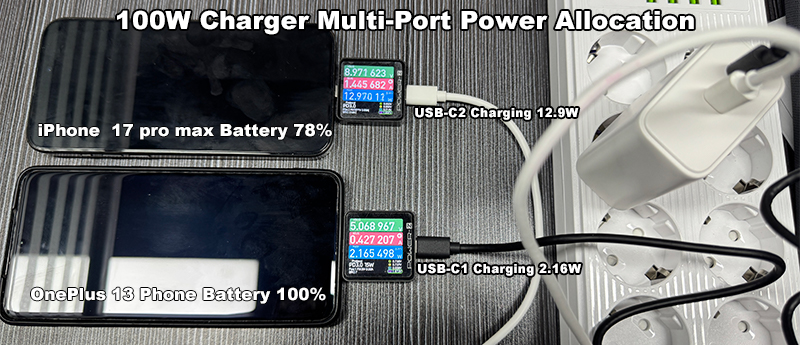
The same principle applies to 100W chargers, but the engineering margin becomes more important. Consider a 100W multi-port charger.
The product may have:
USB-C1: 100W maximum
USB-C2: 30W or another allocated output
USB-A: 18W or 30W
Once multiple ports are used simultaneously, the charger no longer maintains a single, fixed 100W output; a power allocation strategy is then required.
For example, a ZONSAN 100W 3C1A desktop charger specifies different output capabilities and combined-port power allocations depending on which ports are being used.
This is where PD protocol tuning and power allocation logic start to overlap.
What Happens When Two Devices Are Connected?
Suppose there is a 100W charger equipped with two USB-C ports, and a laptop is connected to the C1 port. The laptop requests a high-power output configuration, and subsequently, a mobile phone is connected to the C2 port. At this point, the charger must manage both loads simultaneously.
The question becomes: How should the available power be divided?
Possible strategies include:
• Priority to C1
• Fixed maximum for C2
• Dynamic power allocation
• Reduced output on C1
• Re-negotiation after the second device connects
The correct solution depends on specific product specifications; there is no single, universal "best" allocation scheme. However, for commercial chargers, performance must be predictable.
A user should not see random charging interruptions every time another device is connected.
Why Multi-Port PD Tuning Needs More Testing
Single-port chargers are relatively straightforward to understand, as they have only one main output path. Multi-port chargers, on the other hand, involve a wider range of potential operating states.
For example: USB-C1 only / USB-C2 only / USB-A only / C1 + C2 / C1 + A / C2 + A / C1 + C2 + A
Each combination can create a different power distribution.
For a 100W or 140W charger, this can become a significant validation task. This is why a product specification should clearly define both: Single-port output and Combined-port output.
A vague statement such as “100W total output” does not tell the buyer enough.
PD and PPS: What Is the Difference?
PD and PPS are closely related, but they are not the same thing.
USB PD provides defined power delivery profiles.
PPS — Programmable Power Supply — allows more flexible voltage adjustment within supported ranges.
This can be useful for compatible smartphones and other devices because the charger can adjust output voltage more precisely rather than relying only on fixed voltage steps.
A charger may support a PPS range such as: 3.3V–11V or 3.3V–21V depending on the design.
This is one reason many modern fast chargers advertise: PD + PPS rather than PD alone.
For a charger manufacturer, supporting PPS also means the power stage and control system need to respond properly to changing voltage/current requests.
Does Every 65W Charger Need PPS?
No. The answer depends on the target market and target devices.
If the product is designed for a specific customer segment that benefits from PPS, it can be an important requirement (Samsung Devices). But adding every possible protocol to a charger does not automatically make it better.
A better engineering approach is: Define the target devices first, then define the required protocols.
Not: Add every protocol available and hope it sells.
What Happens If PD Negotiation Fails?
This is where charger protection and fallback behavior become important. A charger should not simply stop functioning because a connected device does not negotiate the expected profile.
Depending on the system design, the charger may fall back to a lower or default output condition.
Engineers need to consider situations such as: Unsupported device, Invalid request, Cable problem, Sudden load change, Over-current, Over-temperature, Short circuit, Device disconnect.
The charger should respond in a controlled way.
This is particularly important for products intended for international B2B distribution. A charger sold across several markets may be connected to thousands of different combinations of devices and cables.
That is very different from testing one reference device in a laboratory.
Why the Cable Matters During PD Testing
A common misconception is focusing solely on the charger itself; the cable is also part of the charging system.
For higher-power USB-C charging, the cable's current capability can affect the available charging power. This is why a charger development team may need to test different cables rather than assuming that every USB-C cable behaves identically.
For higher-power products, the engineering team may also need to consider cable identification and current capability as part of the complete system.
So when developing a: 65W USB-C PD charger or 100W GaN PD charger, the testing plan should include the charger, cable and target device together.
* 3A, 5A and 6A charging cables
PD Protocol Tuning Is an Iterative Process
One of the biggest misunderstandings about charger development is the idea that engineers configure the PD profiles once and the job is finished.
Real development is usually more iterative. A simplified development loop can look like:
Initial PD Configuration → Prototype Test → Device Compatibility Test → Load Test
↓
Validation ← Retest ← Engineering Adjustment ← Protection Test ← Thermal Tes
That cycle may repeat several times. Sometimes the problem is not actually the PD protocol.
It may be: Power-stage response; Component tolerance; Thermal limitation; Cable behavior; PCB layout; EMI issue; Firmware/configuration; Protection threshold. This is why PD tuning should be handled by an engineering team that understands the entire charger rather than treating protocol configuration as an isolated task.
What Should a Charger Buyer Ask the Factory About PD?
If you are sourcing a custom charger, you do not necessarily need to understand every PD message.
But you should ask practical questions.
1. Which PD profiles does the charger support?
2. Does it support PPS?
3. Which devices have been tested?
4. What happens when multiple ports are used?
5. How is power allocated?
6. What happens when the load changes?
7. What cable requirements apply?
8. Has the final configuration been validated?
9. Are the PD parameters adjustable during development?
10. Can the factory support custom PD requirements?
These questions will tell you much more about a manufacturer's engineering capability than simply asking: “Do you make PD chargers?”
What Makes a Good PD Charger Manufacturer?
A capable USB-C PD charger factory should not only know how to produce a charger.
It should understand the interaction between:
• PD protocol, Power electronics, Thermal design, PCB layout, USB-C interface, Protection, Certification, Mass production.
This becomes especially important for custom products. A factory may be able to produce a standard 20W charger efficiently. That does not automatically mean it can develop a stable 100W multi-port PD charger.
The engineering challenge changes with the power level and product architecture. ZONSAN's current product range extends from 5W to 240W and includes USB-C PD, GaN (Learn about GaN 1, GaN 2 and GaN 3), QC and PPS solutions, providing a useful example of why charger development capability needs to cover more than a single power category.
PD 3.0 vs. PD 3.1: What Changes for Charger Development?
For charger buyers, the easiest way to understand the difference is to look at power capability.
USB PD 3.1 expanded USB-C Power Delivery beyond the previous 100W level and introduced Extended Power Range, or EPR. USB-IF states that PD 3.1 enables USB-C Power Delivery applications up to 240W, with fixed voltage levels of 28V, 36V and 48V for higher-power applications.
That changes the engineering requirements for high-power chargers. A 65W charger and a 140W charger may both use USB-C PD, but the power architecture, thermal requirements, cable considerations and validation work are not the same.
For a PD charger manufacturer, this distinction matters from the beginning of the project.
* PD3.0 vs PD3.1 vs PD3.2 (AVS): The Future of USB-C Charging
What Is EPR in USB PD 3.1?
EPR stands for Extended Power Range. Before PD 3.1, USB-C PD power delivery was generally associated with the 100W range.
PD 3.1 extended the specification to higher power levels. The USB-IF specification describes new fixed voltage levels of: 28V, 36V, 48V, which can support up to 140W, 180W and 240W respectively.
This is one reason you will now see products described as:
👉140W PD 3.1 charger
👉180W USB-C charger
👉240W USB-C PD charger
👉PD 3.1 GaN charger
But a higher number on the product label does not automatically mean a better charger. The complete electrical and thermal design still matters.
What Are PDO and APDO?
These two terms often appear in technical discussions about PD.
PDO means Power Data Object. It describes a power capability or operating condition that the charger can advertise.
A charger may advertise several fixed power options. For example: 5V, 9V, 12V,15V, 20V. Depending on the implementation, higher-voltage EPR profiles may also be available.
APDO, or Augmented Power Data Object, is associated with more flexible power delivery modes, including PPS. This gives compatible devices more flexibility when requesting voltage and current.
For charger engineers, these objects are not just technical terminology. They determine what the charger tells the connected device it can actually provide.
How PPS Tuning Differs From Fixed PD Profiles
Imagine two chargers.
Charger A — It provides fixed options: 5V → 9V → 12V → 15V → 20V
Charger B — It also supports PPS.
A compatible device can request an adjustable voltage within the supported PPS range. This can make power delivery more flexible.
However, PPS does not mean the charger can output any voltage or current without limits.
The PPS range is defined by the charger's actual implementation. For example, a product may specify: PPS: 3.3–11V / 5A
while another charger may support a different range. This is why a buyer should look at the actual PPS specification rather than simply seeing the words: “PD + PPS.”
Why PPS Matters for Fast-Charging Compatibility
Many modern smartphones use charging systems that benefit from PPS. That means a charger designed primarily for smartphones may have different protocol requirements from one designed primarily for laptops.
For a 45W charger manufacturer, for example, the engineering target could be: USB-C PD + PPS + compact size + smartphone compatibility.
A 65W laptop charger may have a different priority: USB-C PD + PPS + 20V output + sustained load + thermal stability.
Both products can be called “fast chargers”, but the engineering objectives are different.
Common PD Negotiation Problems (my electronic device won't charge)
Not every PD problem is caused by the same thing. Some common issues include:
1. Device Does Not Fast Charge, Possible causes include:
• Unsupported PD profile
• PPS mismatch
• Cable limitation
• Device-specific charging behavior
• Incorrect configuration
2. Charging Starts and Stops, Possible causes may include:
• Protection triggering
• Thermal limitation
• Unstable power conversion
• Incorrect negotiation behavior
• Cable or connector problems
3. One Device Works but Another Does Not
This is a classic compatibility issue. A charger can work perfectly with one laptop but behave differently with another.
That is why compatibility testing should cover multiple target devices.
4. Multi-Port Charging Reduces Power Unexpectedly
This may simply be the intended power-sharing strategy.
This issue is not necessarily a defect; the key is whether this behavior complies with the published specifications.
5. PPS Does Not Work as Expected
The charger may advertise PPS, but the connected device may not use it.
The device must also support the required PPS range. Again, “supports PPS” does not mean every device will use PPS.

How a Factory Tests PD Compatibility
A professional development process normally uses more than a USB power meter. For deeper debugging, engineers can use dedicated USB PD protocol analysis and compliance equipment.
USB-IF currently provides dedicated USB Type-C and Power Delivery testing resources, including protocol, physical-layer and power-supply testing. Its current compliance resources also include EPR-capable test solutions.
A PD charger factory's internal engineering test may include:
Protocol Test — Check communication and negotiation.
Load Test — Apply controlled loads to different power levels.
Compatibility Test — Connect different phones, tablets, laptops and accessories.
Thermal Test — Observe temperature under sustained load.
Protection Test — Check abnormal conditions.
Multi-Port Test — Test every major port combination.
The goal is to find problems before certification and mass production.
PD Compliance Is Different From Internal Factory Testing
This distinction is important for B2B buyers.
The factory may conduct internal engineering verification, but this does not automatically mean the product has passed formal USB-IF compliance testing.
USB-IF maintains a dedicated Power Delivery Compliance Test Specification and approved test solutions. Its document library currently includes the USB PD Revision 3.2 specification and a Q3 2026 PD Compliance Test Specification.
So when evaluating a supplier, ask: What internal tests have you performed? and separately: What formal certifications or compliance tests apply to the final product?
These are two different questions.
PD 3.1 PD3.2 and 140W Charger Development
A 140W charger is a good example of why protocol tuning and power electronics need to be developed together.
ZONSAN currently lists a 140W PD 3.1 GaN charger with USB-C outputs supporting 20V/5A and a 28V/5A profile, plus PPS up to 21V/5A. The product also specifies multiple combined-port power configurations.
That is important because the product is not simply: “140W output.”
It is a complete system involving: PD 3.1 / PD3.2, EPR, PPS, GaN power conversion, Thermal management, Multi-port power allocation, and Protection.
That is the level of engineering detail buyers should expect when sourcing a high-power charger.
Why 140W Is Different From 100W
A 140W charger can use a higher EPR voltage profile. USB-IF defines 28V as one of the fixed EPR voltage levels associated with up to 140W.
When looking for a manufacturer of 140W chargers, it is worth verifying whether the supplier has genuine experience in developing high-power PD 3.1 products; a factory that mainly produces 20W phone chargers may not have the same engineering experience.
Similarly, when purchasing such products on e-commerce platforms, one should confirm whether they actually deliver 140W of charging power (A 140W GaN charger priced at $15—the power rating is essentially fake).
What Should a B2B Buyer Include in a PD Charger RFQ?
A good RFQ makes the engineering conversation much easier.
Instead of writing: “Please quote 100W PD charger.”
Provide more information. For example:
Product: 100W GaN USB-C charger
Ports: 2C1A
Power: 100W total
Protocols: PD + PPS
Target devices: Laptop + smartphone + tablet +usb mobile devices
Plug: EU / UK / US / KR
Target market: Europe / UK / US / BR / Korea
Certification: CE / RoHS / CB / UKCA / ANATEL / KC / FCC
Color(Casing or USB port): Black, White, and Customs
Logo: Yes
Packaging: Custom
MOQ: 1,000 pcs or more
This gives the factory enough information to determine whether an existing ODM platform is suitable or whether a new OEM development is needed.
ZONSAN describes itself as a charger manufacturer focused on OEM/ODM development(17 years of experience) and lists charger products across a 5W–240W range, including PD, PPS, GaN and higher-power PD 3.1/PD3.2 AVS products.
For a B2B buyer, that kind of power-range experience is more useful when it is supported by actual engineering and validation capability.
How to Evaluate a 65W, 100W or 140W PD Charger Factory
A simple comparison can help.
| Evaluation Area | 65W | 100W | 140W |
| PD | Important | Critical | Critical |
| PPS | Often important | Often important | Important |
| Thermal design | Important | Very important | Critical |
| Multi-port allocation | Depends on design | Very important | Very important |
| PD 3.1 EPR | Not normally required | Depends on product | Important |
| Cable consideration | Important | Important | Critical |
| Long-duration load testing | Important | Critical | Critical |
| Protocol analysis | Recommended | Strongly recommended | Essential for serious development |
| Factory experience | Important | Very important | Critical |
This is not a certification checklist. It is simply a practical way to think about engineering complexity.
Final Takeaway: PD Tuning Is About Behavior, Not Just Wattage
A charger specification may say: 65W, 100W or 140W. But the number alone tells only part of the story.
A good USB-C PD charger needs to behave correctly when:
• A device connects
• A device requests power
• The requested power changes
• Another device is connected
• The load suddenly changes
• The charger becomes hot
• A cable is removed
• A protection condition occurs
That is what PD protocol tuning is really about.
For simple chargers, this process might be relatively straightforward. However, for custom 65W PD chargers, 100W GaN chargers, or 140W PD 3.1 chargers, the protocol forms part of a much larger engineering system.
The best result comes when the PD controller, power stage, thermal design, firmware/configuration, USB-C interface and protection system are developed and validated together. And for a B2B buyer, that is one of the most useful ways to evaluate a custom charger manufacturer.
Do not only ask: “How many watts?” Ask: “How does the charger behave?”
That question usually leads to a much better product.
FAQ: PD Protocol Tuning in Custom Charger Development
Q1: What is PD protocol tuning?
PD protocol tuning is the engineering process of configuring and validating how a USB-C charger advertises power capabilities, negotiates with devices and responds to changing power requests.
Q2: Does a 100W charger always charge a laptop at 100W?
No. The connected device determines how much power it requests within the charger's supported capabilities.
Q3: What is the difference between PD 3.0 and PD 3.1?
PD 3.1 expanded USB Power Delivery into higher-power applications through EPR, enabling USB-C PD applications up to 240W.
Q4: What is EPR?
EPR means Extended Power Range. It is the higher-power range introduced with USB PD 3.1.
Q5: What is PPS?
PPS stands for Programmable Power Supply. It allows compatible devices to request adjustable voltage within the charger's supported PPS range.
Q6: Does every PD charger support PPS?
No. PPS is an additional capability and should be listed separately in the product specification.
Q7: Can PD parameters be customized?
Depending on the controller and charger architecture, PD parameters can often be configured during development. The available options depend on the specific platform.
Q8: Why does multi-port charging require more PD testing?
Because the charger must manage different loads and power requests at the same time. Each port combination can create a different operating condition.
Q9: Does a 140W charger require PD 3.1?
A 140W USB-C charger using the higher EPR power range would require an appropriate PD 3.1 implementation. USB-IF defines 28V as an EPR fixed voltage level supporting applications up to 140W.
Q10: How should I choose a PD charger manufacturer?
Look at actual PD development experience, protocol testing, device compatibility, thermal engineering, certification support, multi-port power allocation and mass-production capability—not only the advertised wattage.
Q11: Can a factory customize a 65W or 100W PD charger?
Yes, depending on the existing platform and required changes. A manufacturer may adapt an existing ODM platform or develop a more customized OEM solution.
Q12: Can ZONSAN develop high-power PD chargers?
ZONSAN currently lists charger products from 5W to 240W and includes PD, PPS, GaN, PD 3.1, PD3.2 and AVSproducts in its range.
Reviewers by: Zonsan Sales Team and Engineers – Emma and Michael
Last Review Date: [September 01, 2026]
Final Takeaway: PD Tuning Is About Behavior, Not Just Wattage
A charger specification may say: 65W, 100W or 140W. But the number alone tells only part of the story.
A good USB-C PD charger needs to behave correctly when:
• A device connects
• A device requests power
• The requested power changes
• Another device is connected
• The load suddenly changes
• The charger becomes hot
• A cable is removed
• A protection condition occurs
That is what PD protocol tuning is really about.
For simple chargers, this process might be relatively straightforward. However, for custom 65W PD chargers, 100W GaN chargers, or 140W PD 3.1 chargers, the protocol forms part of a much larger engineering system.
The best result comes when the PD controller, power stage, thermal design, firmware/configuration, USB-C interface and protection system are developed and validated together. And for a B2B buyer, that is one of the most useful ways to evaluate a custom charger manufacturer.
Do not only ask: “How many watts?” Ask: “How does the charger behave?”
That question usually leads to a much better product.
FAQ: PD Protocol Tuning in Custom Charger Development
Q1: What is PD protocol tuning?
PD protocol tuning is the engineering process of configuring and validating how a USB-C charger advertises power capabilities, negotiates with devices and responds to changing power requests.
Q2: Does a 100W charger always charge a laptop at 100W?
No. The connected device determines how much power it requests within the charger's supported capabilities.
Q3: What is the difference between PD 3.0 and PD 3.1?
PD 3.1 expanded USB Power Delivery into higher-power applications through EPR, enabling USB-C PD applications up to 240W.
Q4: What is EPR?
EPR means Extended Power Range. It is the higher-power range introduced with USB PD 3.1.
Q5: What is PPS?
PPS stands for Programmable Power Supply. It allows compatible devices to request adjustable voltage within the charger's supported PPS range.
Q6: Does every PD charger support PPS?
No. PPS is an additional capability and should be listed separately in the product specification.
Q7: Can PD parameters be customized?
Depending on the controller and charger architecture, PD parameters can often be configured during development. The available options depend on the specific platform.
Q8: Why does multi-port charging require more PD testing?
Because the charger must manage different loads and power requests at the same time. Each port combination can create a different operating condition.
Q9: Does a 140W charger require PD 3.1?
A 140W USB-C charger using the higher EPR power range would require an appropriate PD 3.1 implementation. USB-IF defines 28V as an EPR fixed voltage level supporting applications up to 140W.
Q10: How should I choose a PD charger manufacturer?
Look at actual PD development experience, protocol testing, device compatibility, thermal engineering, certification support, multi-port power allocation and mass-production capability—not only the advertised wattage.
Q11: Can a factory customize a 65W or 100W PD charger?
Yes, depending on the existing platform and required changes. A manufacturer may adapt an existing ODM platform or develop a more customized OEM solution.
Q12: Can ZONSAN develop high-power PD chargers?
ZONSAN currently lists charger products from 5W to 240W and includes PD, PPS, GaN, PD 3.1, PD3.2 and AVSproducts in its range.
Reviewers by: Zonsan Sales Team and Engineers – Emma and Michael
Last Review Date: [September 01, 2026]