How Safety Standards Affect Charger Design
When people look at a USB-C charger, they usually see a small plastic housing, a few ports and a power rating such as 30W, 65W or 100W.
The engineering team sees something very different.
Inside that small housing are high-voltage circuits, isolation barriers, switching components, a transformer, protection circuits, thermal paths and a USB-C power delivery system. Every part has to work together while remaining safe under normal operation and reasonably foreseeable abnormal conditions.
This is where safety standards begin to influence charger design.
Safety standards are not something a charger manufacturer deals with after the product has already been designed. They can affect the PCB layout, transformer construction, insulation system, component selection, enclosure, temperature management and even the way the finished charger is tested on the production line.
For GaN fast chargers, this becomes increasingly important.
A compact 65W GaN charger has to manage more power in a smaller space than many older low-power adapters. A 100W or 140W multi-port charger adds further complexity because several outputs may be operating simultaneously.
The result is simple: Safety requirements are part of charger engineering from the beginning.
Quick Answer: How Do Safety Standards Affect Charger Design?
Safety standards affect charger design by influencing:
• Electrical isolation, Creepage and clearance, Transformer construction, Insulation materials,PCB layout, Protection circuits.
• Component ratings, Thermal design, Enclosure materials, Mechanical construction, Abnormal-condition behavior, Production-line safety testing, Documentation and change control.
The exact requirements depend on the product, target market and applicable standard.
For chargers and external power supplies, IEC 62368-1 is particularly relevant to the safety architecture of equipment in its scope. The standard uses an energy-source and safeguard approach rather than simply prescribing one fixed design.
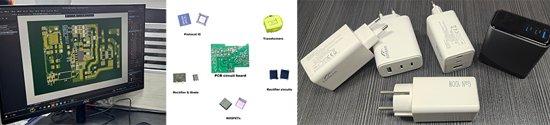
why two chargers with the same 65W output can have very different internal designs.
What Is a Charger Safety Standard?
A safety standard provides a structured set of requirements for reducing risks associated with electrical and electronic equipment.
It does not simply ask: “Does this charger output 65W?”
It asks much deeper questions.
For example:
• Can hazardous voltage reach a user-accessible part?
• Is the isolation system adequate?
• Can a component overheat under abnormal conditions?
• Does the enclosure provide the required protection?
• Does the charger respond safely to faults?
• Are critical components appropriately rated?
• Can the product maintain its safety characteristics during production?
IEC 62368-1:2023 describes itself as a product safety standard that classifies energy sources and specifies safeguards intended to reduce the likelihood of pain, injury and fire-related property damage.
The factory is not merely designing electrical performance; it is building a comprehensive safety system.
Safety Standards Do Not Exist in Isolation
Another important point is that charger compliance usually involves more than one requirement.
A modern USB-C charger can involve several technical areas:
• Product safety, Electromagnetic compatibility,Energy efficiency.
• USB-C requirements, USB Power Delivery, Regional regulatory requirements, Environmental requirements
These areas overlap, but they are not identical.
For example, USB-IF maintains separate USB Type-C and Power Delivery specifications and compliance test requirements. Its current document library includes USB PD Revision 3.2 and a Q3 2026 PD Compliance Test Specification.
So a charger manufacturer needs to distinguish between: Safety compliance and Protocol or interface compliance.
A charger can be electrically safe but still have a USB-C or PD implementation problem. Likewise, a charger can negotiate power correctly while having a weakness in its insulation or thermal design.
1. Safety Standards Affect the Charger Architecture
The first major effect happens before the PCB is even routed. Engineers need to decide how the power conversion system will be structured.
A typical AC-to-DC charger includes:
AC input → protection → rectification → switching stage → transformer → secondary conversion → output filtering → USB-C output
Safety considerations influence the separation between these sections.
The primary side handles potentially hazardous mains voltage.
The secondary side is connected to the USB output that the user touches and connects to electronic devices. (That separation is fundamental.)
Therefore, when designing the architecture, the engineering team must ensure that the necessary safety isolation barriers are maintained. This requirement influences component placement, PCB routing, and the structural design of the transformer from the very beginning.
2. PCB Layout Is Directly Affected by Safety Requirements
A charger PCB is not simply a space where components are placed according to electrical convenience.
Safety requirements influence where components can physically sit.
Engineers need to pay attention to:
• High-voltage areas and Low-voltage areas;
• Isolation boundaries, Creepage and Clearance;
• PCB slots where applicable;
• Component spacing, Routing and Heat-producing components;
• Grounding.
This becomes challenging when the charger is very small.
A compact 30W adapter may have enough room to separate critical areas comfortably.
A high-density 100W GaN charger has much less freedom.
The PCB designer is therefore solving several problems simultaneously: How do I make the circuit electrically efficient while keeping the required safety separation and thermal performance?
That is an engineering problem, not simply a layout problem.
You can browse Zonsan's previously published articles here: The Importance of Charger PCB Design.↗
3. Creepage and Clearance Influence Component Placement
Creepage and clearance are two of the most important concepts in charger safety design.
Clearance refers to the shortest distance through air between conductive parts.
Creepage refers to the shortest distance along an insulating surface.
Do not confuse these two concepts.
Engineers need to consider these distances around areas where different electrical potentials exist, especially between hazardous primary circuits and accessible secondary circuits.
This can influence:
• PCB component placement, Copper routing, and Transformer pin assignments;
• PCB slots, Optocoupler placement, Connector positioning, and Insulation structures;
A charger may look perfectly organized on the PCB while still requiring a redesign if the relevant safety distances are not adequate for the applicable construction.
That is why safety review needs to happen during PCB development.
4. Transformer Design Is Heavily Influenced by Safety
The transformer is one of the most important components in an isolated charger. It is responsible for energy transfer while helping maintain the separation between primary and secondary circuits.
Therefore, safety considerations influence the winding structure, insulation system, wire type, bobbin design, insulating tape, magnetic core, pin configuration, and primary-to-secondary isolation.
This is particularly important in compact Gallium Nitride (GaN) chargers.
The transformer has to fit into a small mechanical envelope without compromising the electrical isolation system. At the same time, it has to handle the required power and thermal conditions.
This is one reason why simply replacing the transformer with a smaller part is not a harmless mechanical change. It can affect electrical performance, thermal behavior and safety.
A safety standard provides a structured set of requirements for reducing risks associated with electrical and electronic equipment.
It does not simply ask: “Does this charger output 65W?”
It asks much deeper questions.
For example:
• Can hazardous voltage reach a user-accessible part?
• Is the isolation system adequate?
• Can a component overheat under abnormal conditions?
• Does the enclosure provide the required protection?
• Does the charger respond safely to faults?
• Are critical components appropriately rated?
• Can the product maintain its safety characteristics during production?
IEC 62368-1:2023 describes itself as a product safety standard that classifies energy sources and specifies safeguards intended to reduce the likelihood of pain, injury and fire-related property damage.
The factory is not merely designing electrical performance; it is building a comprehensive safety system.
Safety Standards Do Not Exist in Isolation
Another important point is that charger compliance usually involves more than one requirement.
A modern USB-C charger can involve several technical areas:
• Product safety, Electromagnetic compatibility,Energy efficiency.
• USB-C requirements, USB Power Delivery, Regional regulatory requirements, Environmental requirements
These areas overlap, but they are not identical.
For example, USB-IF maintains separate USB Type-C and Power Delivery specifications and compliance test requirements. Its current document library includes USB PD Revision 3.2 and a Q3 2026 PD Compliance Test Specification.
So a charger manufacturer needs to distinguish between: Safety compliance and Protocol or interface compliance.
A charger can be electrically safe but still have a USB-C or PD implementation problem. Likewise, a charger can negotiate power correctly while having a weakness in its insulation or thermal design.
1. Safety Standards Affect the Charger Architecture
The first major effect happens before the PCB is even routed. Engineers need to decide how the power conversion system will be structured.
A typical AC-to-DC charger includes:
AC input → protection → rectification → switching stage → transformer → secondary conversion → output filtering → USB-C output
Safety considerations influence the separation between these sections.
The primary side handles potentially hazardous mains voltage.
The secondary side is connected to the USB output that the user touches and connects to electronic devices. (That separation is fundamental.)
Therefore, when designing the architecture, the engineering team must ensure that the necessary safety isolation barriers are maintained. This requirement influences component placement, PCB routing, and the structural design of the transformer from the very beginning.
2. PCB Layout Is Directly Affected by Safety Requirements
A charger PCB is not simply a space where components are placed according to electrical convenience.
Safety requirements influence where components can physically sit.
Engineers need to pay attention to:
• High-voltage areas and Low-voltage areas;
• Isolation boundaries, Creepage and Clearance;
• PCB slots where applicable;
• Component spacing, Routing and Heat-producing components;
• Grounding.
This becomes challenging when the charger is very small.
A compact 30W adapter may have enough room to separate critical areas comfortably.
A high-density 100W GaN charger has much less freedom.
The PCB designer is therefore solving several problems simultaneously: How do I make the circuit electrically efficient while keeping the required safety separation and thermal performance?
That is an engineering problem, not simply a layout problem.
You can browse Zonsan's previously published articles here: The Importance of Charger PCB Design.↗
3. Creepage and Clearance Influence Component Placement
Creepage and clearance are two of the most important concepts in charger safety design.
Clearance refers to the shortest distance through air between conductive parts.
Creepage refers to the shortest distance along an insulating surface.
Do not confuse these two concepts.
Engineers need to consider these distances around areas where different electrical potentials exist, especially between hazardous primary circuits and accessible secondary circuits.
This can influence:
• PCB component placement, Copper routing, and Transformer pin assignments;
• PCB slots, Optocoupler placement, Connector positioning, and Insulation structures;
A charger may look perfectly organized on the PCB while still requiring a redesign if the relevant safety distances are not adequate for the applicable construction.
That is why safety review needs to happen during PCB development.
4. Transformer Design Is Heavily Influenced by Safety
The transformer is one of the most important components in an isolated charger. It is responsible for energy transfer while helping maintain the separation between primary and secondary circuits.
Therefore, safety considerations influence the winding structure, insulation system, wire type, bobbin design, insulating tape, magnetic core, pin configuration, and primary-to-secondary isolation.
This is particularly important in compact Gallium Nitride (GaN) chargers.
The transformer has to fit into a small mechanical envelope without compromising the electrical isolation system. At the same time, it has to handle the required power and thermal conditions.
This is one reason why simply replacing the transformer with a smaller part is not a harmless mechanical change. It can affect electrical performance, thermal behavior and safety.

5. Component Selection Becomes More Controlled
Safety standards also change the way a charger factory selects components.
Engineers cannot look only at Voltage, Current, Cost, Size. They also need to consider the component's role in the safety architecture.
Depending on the circuit, important components include:
• Fuses, Safety capacitors, Transformers, and Optocouplers.
• Power switches, GaN devices, Rectifiers, Thermal protection components and Insulation materials.
The purchasing department might find components with nearly identical electrical specifications, but that does not mean they can serve as direct replacements.
The replacement may have different construction, ratings, insulation characteristics or certification status.(Here, you can quickly gain a detailed understanding of components such as charger PCBs and transformers.)
This is why professional charger manufacturers employ a controlled Bill of Materials (BOM) for various designs subject to certification requirements.
6. Protection Circuits Are Part of the Safety Design
A charger needs to behave safely when everything is working normally.
It also needs to behave safely when something goes wrong.
That is where protection circuits become important.
Depending on the design, these include: Over-voltage protection, Over-current protection, Short-circuit protection, Over-temperature protection, Input surge protection and Output protection
The engineering question is not simply whether a protection function exists. It is:
What happens when the protection function is triggered?
Does the charger shut down?
Does it recover automatically?
Does it limit current?
Does the temperature continue rising?
Does the output remain within the expected range?
These behaviors need to be understood and verified during development.
7. Thermal Design Is Becoming More Important
Safety standards have a strong practical impact on thermal design.
The higher the power density, the more difficult it becomes to keep internal temperatures under control. This is one of the reasons GaN technology has changed charger engineering.
GaN can support higher-frequency switching and help manufacturers achieve higher power density, but the resulting compact design still has to deal with heat.
Engineers therefore consider:
• Power semiconductor losses, Transformer temperature;
• PCB copper area, Thermal conduction, Component spacing;
• Enclosure heat transfer, Air movement, Hotspot location.
A charger's quality cannot be judged solely by its average surface temperature; the operating temperatures of critical components may be significantly higher than the casing temperature.(Inside Temperature Rise Testing for Fast Chargers.)
Professional charger manufacturers typically conduct component-level temperature measurements during the development process.
8. The Enclosure Becomes Part of the Safety System
The plastic housing is often treated as the cosmetic part of the charger. From an engineering perspective, that is incomplete.
The enclosure can influence:
• Protection against contact;
• Mechanical strength, Heat transfer;
• Fire behavior, Component positioning;
• Internal clearances, Structural integrity;
Material selection therefore matters!
The factory needs to consider whether the selected housing material and construction are appropriate for the intended application and applicable requirements.
The mechanical engineer also needs to work with the electrical engineer. Moving an internal component by only a few millimeters may improve cooling. But it may also change spacing.
Changing the wall thickness may affect heat dissipation.
Changing the housing geometry may change internal component positions.
This is why charger development cannot be divided into completely independent electrical and mechanical projects.
9. Plug Design Is Also Part of Charger Safety
The AC plug is another area where safety requirements influence mechanical design.
The engineering team needs to consider:
• Plug structure, Pin strength, Electrical connection;
• Mechanical retention, Insulation, Housing integration, Regional plug configuration.
For foldable or retractable plug chargers, the mechanical system becomes more complex.
The moving mechanism must remain reliable while maintaining the required electrical and mechanical protection.
This is a good example of why safety engineering is not limited to the PCB.
10. Higher Power Means More Engineering Trade-Offs
A common mistake is to assume that increasing a charger from 65W to 100W is simply a matter of using a larger power IC.
It is not.
Increasing power output affects component temperatures, transformer size, PCB copper foil design, switching losses, thermal paths, protection mechanism performance, enclosure temperature, and power density.
If the charger also has multiple ports, the design becomes more complicated again.
The factory needs to determine how power is distributed when multiple outputs operate simultaneously.
Even for 100W chargers, the internal design requirements for the single USB-C port version and the dual USB-C port version differ drastically.
Safety engineering has to account for the actual operating states of the product.
11. USB-C PD Adds Another Layer of Design Requirements
USB-C chargers are not just AC-to-DC power supplies with a different connector. The USB-C interface has its own electrical and protocol requirements.
USB-IF's published test specifications cover USB Type-C source behavior and Power Delivery functions. For example, the Type-C functional test documentation includes requirements around VBUS behavior, current advertisement and USB-PD negotiation.
For a charger manufacturer, this means the USB-C controller and firmware or configuration need to be considered alongside the power stage.
Engineers need to verify:
• Power advertisement, PD negotiation, Output voltage transitions;
• Current limits, Cable-related behavior, Protection response and Multi-port power allocation.
This is especially true for high-power USB PD products.
USB-IF's current compliance program also distinguishes between standard power range and extended power range testing for PD-capable products.
So the safety architecture and USB-C power-delivery architecture need to work together.
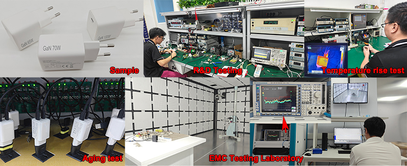
12. Safety Standards Affect Thermal Testing Conditions
One of the less obvious effects of safety requirements is how engineers think about test conditions.
A charger cannot be evaluated only at room temperature with a light load.
Engineers need to understand what happens under demanding operating conditions.
Depending on the applicable product requirements, testing consider factors such as:
• Input voltage, Load level, Ambient conditions;
• Port configuration, Continuous operation, Abnormal operation.
The objective is to understand whether the charger remains within acceptable safety limits.
A 140W charger operating at maximum load for several minutes performs very differently than when it is delivering 30W of power to a smartphone.
13. EMC Requirements Also Influence Charger Design
Safety and EMC are different engineering areas, but they often affect the same physical design decisions.
Fast chargers use high-frequency switching. Poorly controlled switching behavior can create unwanted electromagnetic noise.
Factory Charger R&D Engineers therefore adjust:
• PCB routing, Switching loops, Grounding, and EMI filters
• Transformer construction, Component placement, Switching parameters, etc.
A change intended to improve EMC can sometimes affect efficiency or thermal performance.
Likewise, a change intended to improve efficiency can alter switching noise. This is why charger development involves trade-offs rather than a simple checklist.
14. Safety Requirements Affect the Manufacturing Process
Safety standards do not stop influencing the product once the design is finished. They can also affect production.
If a particular insulation component is critical, the factory needs to control that component during purchasing and assembly.
If a production-line electrical test is required, the factory needs appropriate equipment and procedures.
If a transformer construction is part of the certified design, production needs to reproduce that construction consistently.
This is where manufacturing engineering becomes important.
A charger factory should be able to connect: Approved Design → Approved BOM → Controlled Production → Required Testing → Final QC
Without that connection, a certified design can gradually change during mass production.
* Analysis of GaN Charger Manufacturing Processes
15. Engineering Changes Become More Difficult After Certification
Safety requirements also make engineering change control more important.
Suppose a charger initially used a transformer from a specific supplier, and the purchasing department subsequently identified a lower-priced alternative.
From a business perspective, such a change might appear quite attractive.
However, from an engineering standpoint, the Phone Charger factory must consider the following issues:
• Is the electrical construction identical?
• Is the insulation system identical?
• Are the relevant ratings equivalent?
• Does the change affect thermal performance?
• Does it affect the certified construction?
• Does additional testing or review become necessary?
The same logic applies to:
• Capacitors, Power ICs, GaN devices, Optocouplers;
• PCB materials, Enclosure plastics, Safety components, etc.
This is why a mature charger manufacturer treats certification-related engineering changes differently from ordinary purchasing substitutions.
16. Safety Standards Influence Charger Size
It is widely believed that the miniaturization of chargers relies primarily on the use of smaller components.
In reality, however, reducing the size is far more challenging.
Manufacturers must pack components—such as power electronics, transformers, protection elements, insulation layers, USB-C controllers, thermal pads, and mechanical structures—into a smaller housing without compromising safety margins.
GaN technology helps because it can enable higher power density.
But higher power density also puts more pressure on layout and thermal engineering.
The result is an engineering balance: Smaller size + higher power + acceptable temperature + adequate safety margin
A manufacturer that can achieve all four has stronger engineering capability than one that simply produces a small enclosure.
17. Why the Same Wattage Does Not Mean the Same Safety Design
Two chargers with a nominal rating of 65W feature vastly different internal architectures.
Safety and EMC are different engineering areas, but they often affect the same physical design decisions.
Fast chargers use high-frequency switching. Poorly controlled switching behavior can create unwanted electromagnetic noise.
Factory Charger R&D Engineers therefore adjust:
• PCB routing, Switching loops, Grounding, and EMI filters
• Transformer construction, Component placement, Switching parameters, etc.
A change intended to improve EMC can sometimes affect efficiency or thermal performance.
Likewise, a change intended to improve efficiency can alter switching noise. This is why charger development involves trade-offs rather than a simple checklist.
14. Safety Requirements Affect the Manufacturing Process
Safety standards do not stop influencing the product once the design is finished. They can also affect production.
If a particular insulation component is critical, the factory needs to control that component during purchasing and assembly.
If a production-line electrical test is required, the factory needs appropriate equipment and procedures.
If a transformer construction is part of the certified design, production needs to reproduce that construction consistently.
This is where manufacturing engineering becomes important.
A charger factory should be able to connect: Approved Design → Approved BOM → Controlled Production → Required Testing → Final QC
Without that connection, a certified design can gradually change during mass production.
* Analysis of GaN Charger Manufacturing Processes
15. Engineering Changes Become More Difficult After Certification
Safety requirements also make engineering change control more important.
Suppose a charger initially used a transformer from a specific supplier, and the purchasing department subsequently identified a lower-priced alternative.
From a business perspective, such a change might appear quite attractive.
However, from an engineering standpoint, the Phone Charger factory must consider the following issues:
• Is the electrical construction identical?
• Is the insulation system identical?
• Are the relevant ratings equivalent?
• Does the change affect thermal performance?
• Does it affect the certified construction?
• Does additional testing or review become necessary?
The same logic applies to:
• Capacitors, Power ICs, GaN devices, Optocouplers;
• PCB materials, Enclosure plastics, Safety components, etc.
This is why a mature charger manufacturer treats certification-related engineering changes differently from ordinary purchasing substitutions.
16. Safety Standards Influence Charger Size
It is widely believed that the miniaturization of chargers relies primarily on the use of smaller components.
In reality, however, reducing the size is far more challenging.
Manufacturers must pack components—such as power electronics, transformers, protection elements, insulation layers, USB-C controllers, thermal pads, and mechanical structures—into a smaller housing without compromising safety margins.
GaN technology helps because it can enable higher power density.
But higher power density also puts more pressure on layout and thermal engineering.
The result is an engineering balance: Smaller size + higher power + acceptable temperature + adequate safety margin
A manufacturer that can achieve all four has stronger engineering capability than one that simply produces a small enclosure.
17. Why the Same Wattage Does Not Mean the Same Safety Design
Two chargers with a nominal rating of 65W feature vastly different internal architectures.
| One use | Another may use |
| • A larger housing | • A compact transformer |
| • GaN switching | • GaN switching |
| • More physical spacing | • Higher power density |
| • A simpler single-port design | • Two USB-C ports |
| - | • Dynamic power allocation |
| • Supports 5-7 plugs types (EU, UK, US, KR, BR, AU, JP) | • There are 3-5 types of plugs (EU, US, KR, BR, JP) |
Both are labeled “65W.” But the engineering problems are not the same.
This is also one of the reasons why consumers should not judge the quality of a charger solely based on its power output.
The design architecture behind the wattage matters.
How a Charger Factory Should Build Safety Into Development
A practical development workflow can look like this:
Stage 1 — Requirements
Define target market, power level, port configuration and certification requirements.
Stage 2 — Architecture
Select the power topology, controller, transformer concept and protection strategy.
Stage 3 — PCB and Mechanical Design
Develop the PCB, enclosure and internal component arrangement while checking safety spacing and thermal paths.
Stage 4 — Prototype
Build engineering samples using controlled components and the intended production architecture.
Stage 5 — Pre-Compliance Testing
Perform electrical, thermal, protection and EMC checks before formal certification.
Stage 6 — Certification
Submit representative samples for the required third-party evaluation.
Stage 7 — Production
Maintain the approved construction and required production-line testing.
This is much more reliable than designing the charger first and trying to “make it compliant” afterward.
What This Means for OEM and ODM Charger Buyers
For an OEM customer, safety standards should be discussed at the beginning of the project.
Before approving a custom charger design, it is worth confirming:
• Target markets, Required certifications;
• Power level, Port configuration, USB-C PD requirements;
• Component strategy, Thermal requirements;
• Production testing, Engineering-change procedures.
This requires particular attention when a client requests a custom enclosure.
A new enclosure design affects internal safety clearance considerations.
A new port layout impacts PCB routing.
A smaller enclosure affects thermal dissipation performance.
Different connector specifications also influence the internal PCB structural design.
Addressing these issues early on minimizes the likelihood of encountering unexpected problems later.
Why Safety Engineering Matters More at 100W and Above
Higher-power chargers are pushing the limits of compact charger design.
At 100W, 140W or 240W, the factory is dealing with significantly higher power density than a basic phone charger.
This poses significant challenges regarding thermal management, component ratings, PCB design, transformer construction, power distribution design, protection mechanisms, and internal structure.
USB PD has also expanded the range of power available through USB-C. USB-IF's current specification library lists PD Revision 3.2 Version 1.2, while its current compliance materials include testing for both SPR and EPR products.
As power increases, safety cannot simply be added at the end.
It has to be part of the architecture.
How ZONSAN Uses Safety Engineering in Charger Development
ZONSAN develops and manufactures USB-C, PD, PPS and GaN chargers covering a broad power range, including compact wall chargers and higher-power multi-port solutions.
For a charger manufacturer, safety engineering is closely connected with the rest of the product-development process.
PCB design, transformer selection, thermal management, component control, testing and production quality all influence the final product.
The ZONSAN charger manufacturing plant encompasses production and testing stages such as SMT (Surface Mount Technology), assembly, burn-in, thermal testing, functional testing, and final quality inspection.
For OEM and ODM customers, this integrated approach is important.
Our goal goes beyond simply manufacturing chargers that meet their rated power output; we aim to develop high-quality products that deliver stable power while complying with all safety standards and market regulatory requirements.
What Makes a Safety-Engineered Charger Different?
A well-engineered charger usually shows its quality in places that customers cannot see.
It may have:
• Better-controlled high-voltage areas;
• More disciplined PCB routing, Proper transformer construction;
• Controlled insulation, Better thermal paths;
• More appropriate protection behavior, Controlled critical components;
• Consistent production testing;
None of these features necessarily appear on the front of the package. But together, they determine how the charger behaves over time.
Safety standards are more than just certification requirements; they profoundly influence the engineering design decisions that determine product quality.
Final Thoughts
Safety standards affect charger design much earlier than most buyers realize.
They influence the architecture, PCB layout, transformer, insulation, component selection, thermal design, enclosure and production process.
For compact GaN and high-power USB-C chargers, these requirements become even more important because engineers are trying to fit more power into less physical space.
A good charger manufacturer does not design a product first and think about safety afterward.
The better approach is to build safety considerations into the design from the beginning: requirements → architecture → PCB → transformer → thermal design → protection → testing → production.
Although this approach requires a greater investment of engineering effort in the early stages, it generally ensures that the subsequent product development process is more controllable and predictable.
For OEM and ODM buyers, this is one of the clearest differences between a factory that can assemble chargers and a charger manufacturer with real engineering capability.
FAQ - Fast Charger Safety Standards
Q1: How do safety standards affect charger design?
They influence electrical isolation, PCB layout, creepage and clearance, transformer construction, component selection, thermal management, protection circuits, enclosure design and production testing.
Q2: What safety standard is commonly associated with modern charger design?
IEC 62368-1 is an important product safety standard for equipment within its scope, including relevant external power supply applications. The current IEC publication is IEC 62368-1:2023.
Q3: Why do charger manufacturers care about creepage and clearance?
These distances help maintain appropriate separation between conductive parts at different electrical potentials, particularly between hazardous primary circuits and accessible secondary circuits.
Q4: Does GaN change charger safety requirements?
GaN does not remove the need to meet applicable safety requirements. However, its use in compact high-power designs can create additional challenges involving switching behavior, thermal management, PCB layout and power density.
Q5: Why is transformer design important for charger safety?
The transformer is part of the isolation and power-conversion system. Its winding, insulation and construction can directly affect the safety architecture of an AC-powered charger.
Q6: Does charger wattage affect safety design?
Yes. Higher power generally creates greater thermal and electrical demands. Multi-port chargers also introduce additional power-allocation and operating-state considerations.
Q7: Are USB-C PD requirements the same as charger safety requirements?
No. USB-C and USB PD include interface and power-delivery requirements, while product safety standards address electrical and physical safety. A charger may need to satisfy both areas.
Q8: Why does the charger enclosure matter?
The enclosure can affect user protection, mechanical strength, thermal behavior, fire-related considerations and the physical positioning of internal components.
Q9: Can a charger manufacturer change components after certification?
Not every component change is equivalent. Changes to critical components or certified construction should be reviewed through the manufacturer's engineering and compliance change-control process.
Q10: Why should safety requirements be considered before PCB design is finished?
Because late changes to spacing, transformer construction, insulation, components or thermal paths can require PCB or mechanical redesign. Considering safety early reduces this risk.
Q11: What should an OEM buyer ask a charger manufacturer about safety?
Ask which safety requirements apply to the target market, how the factory performs pre-compliance testing, how critical components are controlled, how engineering changes are handled and how production testing is maintained.
Reviewer: Zonsan R&D and Engineer Assistant — Luis and David
Second Reviewer: Luke, Ken
Final Review Date: [September 10, 2026]
The design architecture behind the wattage matters.
How a Charger Factory Should Build Safety Into Development
A practical development workflow can look like this:
Stage 1 — Requirements
Define target market, power level, port configuration and certification requirements.
Stage 2 — Architecture
Select the power topology, controller, transformer concept and protection strategy.
Stage 3 — PCB and Mechanical Design
Develop the PCB, enclosure and internal component arrangement while checking safety spacing and thermal paths.
Stage 4 — Prototype
Build engineering samples using controlled components and the intended production architecture.
Stage 5 — Pre-Compliance Testing
Perform electrical, thermal, protection and EMC checks before formal certification.
Stage 6 — Certification
Submit representative samples for the required third-party evaluation.
Stage 7 — Production
Maintain the approved construction and required production-line testing.
This is much more reliable than designing the charger first and trying to “make it compliant” afterward.
What This Means for OEM and ODM Charger Buyers
For an OEM customer, safety standards should be discussed at the beginning of the project.
Before approving a custom charger design, it is worth confirming:
• Target markets, Required certifications;
• Power level, Port configuration, USB-C PD requirements;
• Component strategy, Thermal requirements;
• Production testing, Engineering-change procedures.
This requires particular attention when a client requests a custom enclosure.
A new enclosure design affects internal safety clearance considerations.
A new port layout impacts PCB routing.
A smaller enclosure affects thermal dissipation performance.
Different connector specifications also influence the internal PCB structural design.
Addressing these issues early on minimizes the likelihood of encountering unexpected problems later.
Why Safety Engineering Matters More at 100W and Above
Higher-power chargers are pushing the limits of compact charger design.
At 100W, 140W or 240W, the factory is dealing with significantly higher power density than a basic phone charger.
This poses significant challenges regarding thermal management, component ratings, PCB design, transformer construction, power distribution design, protection mechanisms, and internal structure.
USB PD has also expanded the range of power available through USB-C. USB-IF's current specification library lists PD Revision 3.2 Version 1.2, while its current compliance materials include testing for both SPR and EPR products.
As power increases, safety cannot simply be added at the end.
It has to be part of the architecture.
How ZONSAN Uses Safety Engineering in Charger Development
ZONSAN develops and manufactures USB-C, PD, PPS and GaN chargers covering a broad power range, including compact wall chargers and higher-power multi-port solutions.
For a charger manufacturer, safety engineering is closely connected with the rest of the product-development process.
PCB design, transformer selection, thermal management, component control, testing and production quality all influence the final product.
The ZONSAN charger manufacturing plant encompasses production and testing stages such as SMT (Surface Mount Technology), assembly, burn-in, thermal testing, functional testing, and final quality inspection.
For OEM and ODM customers, this integrated approach is important.
Our goal goes beyond simply manufacturing chargers that meet their rated power output; we aim to develop high-quality products that deliver stable power while complying with all safety standards and market regulatory requirements.
What Makes a Safety-Engineered Charger Different?
A well-engineered charger usually shows its quality in places that customers cannot see.
It may have:
• Better-controlled high-voltage areas;
• More disciplined PCB routing, Proper transformer construction;
• Controlled insulation, Better thermal paths;
• More appropriate protection behavior, Controlled critical components;
• Consistent production testing;
None of these features necessarily appear on the front of the package. But together, they determine how the charger behaves over time.
Safety standards are more than just certification requirements; they profoundly influence the engineering design decisions that determine product quality.
Final Thoughts
Safety standards affect charger design much earlier than most buyers realize.
They influence the architecture, PCB layout, transformer, insulation, component selection, thermal design, enclosure and production process.
For compact GaN and high-power USB-C chargers, these requirements become even more important because engineers are trying to fit more power into less physical space.
A good charger manufacturer does not design a product first and think about safety afterward.
The better approach is to build safety considerations into the design from the beginning: requirements → architecture → PCB → transformer → thermal design → protection → testing → production.
Although this approach requires a greater investment of engineering effort in the early stages, it generally ensures that the subsequent product development process is more controllable and predictable.
For OEM and ODM buyers, this is one of the clearest differences between a factory that can assemble chargers and a charger manufacturer with real engineering capability.
FAQ - Fast Charger Safety Standards
Q1: How do safety standards affect charger design?
They influence electrical isolation, PCB layout, creepage and clearance, transformer construction, component selection, thermal management, protection circuits, enclosure design and production testing.
Q2: What safety standard is commonly associated with modern charger design?
IEC 62368-1 is an important product safety standard for equipment within its scope, including relevant external power supply applications. The current IEC publication is IEC 62368-1:2023.
Q3: Why do charger manufacturers care about creepage and clearance?
These distances help maintain appropriate separation between conductive parts at different electrical potentials, particularly between hazardous primary circuits and accessible secondary circuits.
Q4: Does GaN change charger safety requirements?
GaN does not remove the need to meet applicable safety requirements. However, its use in compact high-power designs can create additional challenges involving switching behavior, thermal management, PCB layout and power density.
Q5: Why is transformer design important for charger safety?
The transformer is part of the isolation and power-conversion system. Its winding, insulation and construction can directly affect the safety architecture of an AC-powered charger.
Q6: Does charger wattage affect safety design?
Yes. Higher power generally creates greater thermal and electrical demands. Multi-port chargers also introduce additional power-allocation and operating-state considerations.
Q7: Are USB-C PD requirements the same as charger safety requirements?
No. USB-C and USB PD include interface and power-delivery requirements, while product safety standards address electrical and physical safety. A charger may need to satisfy both areas.
Q8: Why does the charger enclosure matter?
The enclosure can affect user protection, mechanical strength, thermal behavior, fire-related considerations and the physical positioning of internal components.
Q9: Can a charger manufacturer change components after certification?
Not every component change is equivalent. Changes to critical components or certified construction should be reviewed through the manufacturer's engineering and compliance change-control process.
Q10: Why should safety requirements be considered before PCB design is finished?
Because late changes to spacing, transformer construction, insulation, components or thermal paths can require PCB or mechanical redesign. Considering safety early reduces this risk.
Q11: What should an OEM buyer ask a charger manufacturer about safety?
Ask which safety requirements apply to the target market, how the factory performs pre-compliance testing, how critical components are controlled, how engineering changes are handled and how production testing is maintained.
Reviewer: Zonsan R&D and Engineer Assistant — Luis and David
Second Reviewer: Luke, Ken
Final Review Date: [September 10, 2026]