Failure Analysis in Charger Manufacturing: How Factories Find the Root Cause
A charger fails during testing. This sounds simple, but from the manufacturer's perspective, a tricky question immediately follows: Why did it fail?
Finding the defective unit is only the first step. Replacing a component and putting the charger back into production may solve one problem, but it does not necessarily explain why the failure happened in the first place.
A professional charger factory looks deeper.
Was the component itself defective?
Did the SMT process introduce a problem?
Was the electrical parameter already drifting before the failure appeared?
Was the assembly process inconsistent?
Did a design change affect the result?
Was the test method accurate?
Or was several small factors coming together?
This is where failure analysis in charger manufacturing becomes important.
Failure analysis is the engineering process of investigating an actual product or process failure, identifying its verified cause, and using the findings to prevent the same problem from happening again.
For USB-C chargers, especially compact GaN and high-power PD chargers, this work can involve electrical measurements, visual inspection, production records, component analysis, thermal data, testing history, and process investigation.
The goal is not simply to answer: "What failed?"
The more useful question is: "Why did it fail, and what needs to change so it does not happen again?"
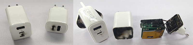
What Is Failure Analysis in Charger Manufacturing?
Failure analysis is a structured investigation performed after an actual failure, nonconformity, abnormal production result, or field problem has been identified.
It is different from ordinary quality inspection. Inspection asks whether a charger meets a defined requirement.
Failure analysis starts when something does not meet that requirement and asks why.
For example, a charger may fail because its USB-C output becomes unstable under high load.
The failure itself is the symptom.
Subsequently, the engineering team determines whether the root cause is related to factors such as components, PCB assemblies, soldering, electrical design, thermal characteristics, firmware or protocol configurations, assembly processes, test equipment, production parameters, materials, supplier variations, engineering changes, or operating conditions.
A professional investigation should not stop at the first plausible explanation; any suspected cause must be supported by evidence.
That distinction is important because the first visible problem is not always the real root cause. ASQ defines root cause analysis as a group of approaches used to uncover the causes of problems, while ISO guidance distinguishes correction from corrective action and emphasizes eliminating the cause of a nonconformity to prevent recurrence.
Failure Analysis vs. PFMEA: They Solve Different Problems
Failure Analysis and PFMEA are closely related, but they happen at different points in the quality process.
PFMEA is proactive. Failure analysis is reactive.
PFMEA asks: What could go wrong?
Failure analysis asks: Why did this actual problem occur?
A simplified comparison looks like this:
| Quality activity | Main question | Typical timing |
| PFMEA | What could fail? | Before or during process planning |
| Control Plan | How should the risk be controlled? | Production planning |
| SPC | Is the process remaining stable? | During production |
| Traceability | What happened to this product and where did it come from? | Throughout production |
| Failure Analysis | Why did this actual failure happen? | After a failure |
| CAPA | What must change to prevent recurrence? | After root cause is confirmed |
This is why failure analysis should not be treated as a replacement for preventive quality engineering. For a deeper look at how factories identify manufacturing risks before mass production, see our guide to PFMEA in Gan Phone Charger Manufacturing.
A strong manufacturing system uses both prevention and investigation. AIAG describes FMEA as a method for identifying potential failures before they occur, while actual failure investigation addresses problems that have already appeared.
Why Failure Analysis Matters for USB-C Chargers
Modern chargers are compact electronic systems rather than simple power adapters.
A compact USB PD GaN charger integrates numerous components, such as AC input circuitry, switching power supply components, transformers, capacitors, MOSFETs or GaN power devices, USB-C PD controllers, protection circuits, feedback circuits, thermal management materials, multiple output ports, firmware-controlled charging functions, and more.
These systems interact with each other. A failure at the output does not necessarily mean the output circuit itself is the source of the problem.
For example, unstable output voltage could be associated with a power-stage issue, feedback behavior, component variation, PCB assembly, thermal conditions, or another upstream condition.
Experienced engineers do not jump to conclusions based solely on fault symptoms; troubleshooting must be guided by evidence.
Step 1 — Define the Failure Clearly
Good failure analysis starts with a precise problem statement. “Charger is bad” is not useful enough.
A better description should include the following information: product model, hardware version, firmware version (if applicable), production batch, test conditions, input conditions, output conditions, fault symptoms, frequency of occurrence, timing of the fault, etc.
For example: USB-C output voltage becomes unstable when the charger operates continuously near rated power under the specified input condition.
That statement gives the engineering team something measurable to investigate. A good failure description also prevents the investigation from becoming too broad. The team knows what happened, under what conditions, and what result was considered abnormal.
Step 2 — Reproduce the Failure
A failure that cannot be reproduced is much harder to analyze. The first objective is therefore to confirm that the reported problem is real and repeatable.
Engineers may repeat the original test under controlled conditions.
Depending on the specific issue, perform input voltage verification, load testing, USB-C PD negotiation, PPS or other charging protocol testing, temperature monitoring, continuous operation testing, connector testing, protection function testing, and output measurements, as well as comparisons with a known good unit.
Doing this is not merely about causing the product to fail again, but rather about determining the precise moment and specific conditions under which the failure occurs.
A failure that occurs only at high load tells engineers something different from a failure that occurs immediately after power-on. Likewise, a failure that appears only after thermal stabilization may point the investigation in a different direction from an immediate electrical failure.
Step 3 — Separate the Symptom From the Cause
This is one of the most important parts of failure analysis. Suppose a charger shuts down during an aging test; “Charger shuts down” is the symptom. It is not automatically the root cause.
The engineering team needs to investigate what happened immediately before the shutdown.
• Component temperature increased beyond the expected range
• Protection circuitry was triggered
• Output regulation became unstable
• A component parameter shifted
• A solder connection became unreliable
• An abnormal load condition occurred
• A thermal interface was not installed correctly
• A process parameter had changed
The investigation continues until the evidence supports a specific cause.
This is also why simply replacing the failed component is often insufficient. If the same process condition remains unchanged, the replacement component may eventually fail in exactly the same way.
Step 4 — Collect Evidence From the Production Process
Failure analysis should not rely solely on engineers' observations of the failed product's visible characteristics; production records often provide important clues.
A professional charger manufacturing system may provide information such as:
• Material batch details, component supplier information, and SMT (Surface Mount Technology) production records;
• AOI (Automated Optical Inspection), ICT (In-Circuit Test), and FCT (Functional Test) results;
• Burn-in test results, electrical test data, and operator or workstation details;
• Production timestamps, equipment information, engineering change details, final inspection records, etc.
This is where manufacturing traceability becomes particularly valuable. Our guide to charger manufacturing traceability explains how factories connect materials, production processes, testing records, and finished products to create a usable production history.
If several failed chargers come from the same production period, engineers can compare their manufacturing history with units that passed.
The question changes from: "What looks wrong with this charger?" to: "What is different between the failed units and the normal units?"
That comparison can dramatically narrow the investigation.
Step 5 — Check the Process Before Blaming the Component
Component failure is an easy explanation. It is also sometimes the wrong explanation.
Suppose a charger has an abnormal solder joint. The investigation should not stop at: "The solder joint is defective."
Engineers should also consider why the solder joint became defective.
• Solder paste condition, printing accuracy, reflow temperature profile, component placement status;
• PCB condition, equipment settings, material variations, process operations, inspection effectiveness;
This is why failure analysis needs to look at the process surrounding the failure, not just the failed part.
The same principle applies to electrical problems. If a charger shows abnormal output behavior, the investigation may need to examine the complete power path rather than replacing one component immediately.
Step 6 — Use Data to Identify Patterns
A single failure is often difficult to interpret, whereas multiple failures may reveal a pattern. This is precisely where production data proves its worth.Engineers may compare:
• Failed units vs. passed units
• Different production batches
• Different component lots
• Different production dates
• Different equipment conditions
• Different process parameters
• Different test results
Suppose a measured parameter gradually moves away from its normal production range before failures increase. That pattern may indicate a process shift rather than a random component failure.
This is one reason SPC is useful alongside failure analysis.
SPC monitors process variation. Failure analysis investigates actual failures.
When the two are connected, engineers can sometimes see both sides of the problem:
• What changed in the process?
• When did it change?
• Did the failure rate change afterward?
• Which production conditions were affected?
Our article on SPC in charger manufacturing goes deeper into how production data can be used to identify abnormal trends before they become larger quality problems.
Step 7 — Use 5 Whys Carefully
The 5 Whys method is simple, but it should not become a mechanical exercise. The idea is to continue asking why until the investigation reaches a cause that can actually be controlled or eliminated.
For example: Problem: Charger failed during aging.
Why? - The internal temperature became too high.
Why? - Heat transfer from the power component was insufficient.
Why? - The thermal interface material was not positioned correctly.
Why? - The assembly process did not adequately control its placement.
Why? - The work instruction did not define the required positioning clearly.
At this point, the investigation has moved beyond the physical symptom. The real corrective action may involve process documentation, assembly control, operator guidance, inspection, or engineering change management.
The important point is that the number five is not magic.
Sometimes asking three questions is enough, while at other times, a more in-depth investigation is required. The objective is to identify a verified and controllable cause, not simply to reach the fifth question.
ISO/IAF guidance specifically notes that investigators should not automatically treat the first failure factor they find as the root cause; possible causes should be examined and confirmed against evidence.
Step 8 — Use Fishbone Analysis When the Cause Is Not Obvious
Some charger failures have several possible contributing factors.
In these cases, a cause-and-effect or fishbone analysis can help organize the investigation.
A manufacturing team may examine categories such as Material, Machine, Method, Measurement, People, Environment.
The value of this method does not lie in the chart itself. Its true value lies in its ability to prevent engineers from prematurely narrowing their focus to a single explanation.
For a charger failure, several possible causes can exist at the same time.
A component may be within specification, while the process applying that component is unstable.
A test may be correct, while the measurement setup is not.
A production process may be stable, while a recent engineering change introduced a new risk.
Failure analysis needs to distinguish between possible causes, contributing factors, and confirmed root causes.
Step 9 — Verify the Suspected Root Cause
Finding a plausible cause is not enough. It needs to be verified!
One practical approach is to reproduce the relationship between the suspected cause and the failure.
For example, if engineers believe a process parameter is causing the failure, they may compare products produced under controlled conditions.
The investigation should answer: If we remove or control this suspected cause, does the failure disappear?
If the answer is no, the investigation is not finished.
If the answer is yes, the team still needs to evaluate whether the result is repeatable and whether other factors could have produced the same outcome.
This verification step is what separates a root-cause investigation from a guess.
A strong manufacturing system uses both prevention and investigation. AIAG describes FMEA as a method for identifying potential failures before they occur, while actual failure investigation addresses problems that have already appeared.
Why Failure Analysis Matters for USB-C Chargers
Modern chargers are compact electronic systems rather than simple power adapters.
A compact USB PD GaN charger integrates numerous components, such as AC input circuitry, switching power supply components, transformers, capacitors, MOSFETs or GaN power devices, USB-C PD controllers, protection circuits, feedback circuits, thermal management materials, multiple output ports, firmware-controlled charging functions, and more.
These systems interact with each other. A failure at the output does not necessarily mean the output circuit itself is the source of the problem.
For example, unstable output voltage could be associated with a power-stage issue, feedback behavior, component variation, PCB assembly, thermal conditions, or another upstream condition.
Experienced engineers do not jump to conclusions based solely on fault symptoms; troubleshooting must be guided by evidence.
Step 1 — Define the Failure Clearly
Good failure analysis starts with a precise problem statement. “Charger is bad” is not useful enough.
A better description should include the following information: product model, hardware version, firmware version (if applicable), production batch, test conditions, input conditions, output conditions, fault symptoms, frequency of occurrence, timing of the fault, etc.
For example: USB-C output voltage becomes unstable when the charger operates continuously near rated power under the specified input condition.
That statement gives the engineering team something measurable to investigate. A good failure description also prevents the investigation from becoming too broad. The team knows what happened, under what conditions, and what result was considered abnormal.
Step 2 — Reproduce the Failure
A failure that cannot be reproduced is much harder to analyze. The first objective is therefore to confirm that the reported problem is real and repeatable.
Engineers may repeat the original test under controlled conditions.
Depending on the specific issue, perform input voltage verification, load testing, USB-C PD negotiation, PPS or other charging protocol testing, temperature monitoring, continuous operation testing, connector testing, protection function testing, and output measurements, as well as comparisons with a known good unit.
Doing this is not merely about causing the product to fail again, but rather about determining the precise moment and specific conditions under which the failure occurs.
A failure that occurs only at high load tells engineers something different from a failure that occurs immediately after power-on. Likewise, a failure that appears only after thermal stabilization may point the investigation in a different direction from an immediate electrical failure.
Step 3 — Separate the Symptom From the Cause
This is one of the most important parts of failure analysis. Suppose a charger shuts down during an aging test; “Charger shuts down” is the symptom. It is not automatically the root cause.
The engineering team needs to investigate what happened immediately before the shutdown.
• Component temperature increased beyond the expected range
• Protection circuitry was triggered
• Output regulation became unstable
• A component parameter shifted
• A solder connection became unreliable
• An abnormal load condition occurred
• A thermal interface was not installed correctly
• A process parameter had changed
The investigation continues until the evidence supports a specific cause.
This is also why simply replacing the failed component is often insufficient. If the same process condition remains unchanged, the replacement component may eventually fail in exactly the same way.
Step 4 — Collect Evidence From the Production Process
Failure analysis should not rely solely on engineers' observations of the failed product's visible characteristics; production records often provide important clues.
A professional charger manufacturing system may provide information such as:
• Material batch details, component supplier information, and SMT (Surface Mount Technology) production records;
• AOI (Automated Optical Inspection), ICT (In-Circuit Test), and FCT (Functional Test) results;
• Burn-in test results, electrical test data, and operator or workstation details;
• Production timestamps, equipment information, engineering change details, final inspection records, etc.
This is where manufacturing traceability becomes particularly valuable. Our guide to charger manufacturing traceability explains how factories connect materials, production processes, testing records, and finished products to create a usable production history.
If several failed chargers come from the same production period, engineers can compare their manufacturing history with units that passed.
The question changes from: "What looks wrong with this charger?" to: "What is different between the failed units and the normal units?"
That comparison can dramatically narrow the investigation.
Step 5 — Check the Process Before Blaming the Component
Component failure is an easy explanation. It is also sometimes the wrong explanation.
Suppose a charger has an abnormal solder joint. The investigation should not stop at: "The solder joint is defective."
Engineers should also consider why the solder joint became defective.
• Solder paste condition, printing accuracy, reflow temperature profile, component placement status;
• PCB condition, equipment settings, material variations, process operations, inspection effectiveness;
This is why failure analysis needs to look at the process surrounding the failure, not just the failed part.
The same principle applies to electrical problems. If a charger shows abnormal output behavior, the investigation may need to examine the complete power path rather than replacing one component immediately.
Step 6 — Use Data to Identify Patterns
A single failure is often difficult to interpret, whereas multiple failures may reveal a pattern. This is precisely where production data proves its worth.Engineers may compare:
• Failed units vs. passed units
• Different production batches
• Different component lots
• Different production dates
• Different equipment conditions
• Different process parameters
• Different test results
Suppose a measured parameter gradually moves away from its normal production range before failures increase. That pattern may indicate a process shift rather than a random component failure.
This is one reason SPC is useful alongside failure analysis.
SPC monitors process variation. Failure analysis investigates actual failures.
When the two are connected, engineers can sometimes see both sides of the problem:
• What changed in the process?
• When did it change?
• Did the failure rate change afterward?
• Which production conditions were affected?
Our article on SPC in charger manufacturing goes deeper into how production data can be used to identify abnormal trends before they become larger quality problems.
Step 7 — Use 5 Whys Carefully
The 5 Whys method is simple, but it should not become a mechanical exercise. The idea is to continue asking why until the investigation reaches a cause that can actually be controlled or eliminated.
For example: Problem: Charger failed during aging.
Why? - The internal temperature became too high.
Why? - Heat transfer from the power component was insufficient.
Why? - The thermal interface material was not positioned correctly.
Why? - The assembly process did not adequately control its placement.
Why? - The work instruction did not define the required positioning clearly.
At this point, the investigation has moved beyond the physical symptom. The real corrective action may involve process documentation, assembly control, operator guidance, inspection, or engineering change management.
The important point is that the number five is not magic.
Sometimes asking three questions is enough, while at other times, a more in-depth investigation is required. The objective is to identify a verified and controllable cause, not simply to reach the fifth question.
ISO/IAF guidance specifically notes that investigators should not automatically treat the first failure factor they find as the root cause; possible causes should be examined and confirmed against evidence.
Step 8 — Use Fishbone Analysis When the Cause Is Not Obvious
Some charger failures have several possible contributing factors.
In these cases, a cause-and-effect or fishbone analysis can help organize the investigation.
A manufacturing team may examine categories such as Material, Machine, Method, Measurement, People, Environment.
The value of this method does not lie in the chart itself. Its true value lies in its ability to prevent engineers from prematurely narrowing their focus to a single explanation.
For a charger failure, several possible causes can exist at the same time.
A component may be within specification, while the process applying that component is unstable.
A test may be correct, while the measurement setup is not.
A production process may be stable, while a recent engineering change introduced a new risk.
Failure analysis needs to distinguish between possible causes, contributing factors, and confirmed root causes.
Step 9 — Verify the Suspected Root Cause
Finding a plausible cause is not enough. It needs to be verified!
One practical approach is to reproduce the relationship between the suspected cause and the failure.
For example, if engineers believe a process parameter is causing the failure, they may compare products produced under controlled conditions.
The investigation should answer: If we remove or control this suspected cause, does the failure disappear?
If the answer is no, the investigation is not finished.
If the answer is yes, the team still needs to evaluate whether the result is repeatable and whether other factors could have produced the same outcome.
This verification step is what separates a root-cause investigation from a guess.

Failure Analysis Should Lead to Corrective Action
Finding the cause is not the end of the process. It is the point where improvement begins.
Once the root cause is confirmed, the factory can determine what needs to change.
Depending on the specific issue, corrective actions include:
• Adjusting process parameters, replacing or re-validating components, improving PCB design, revising work instructions, improving inspection methods, and increasing test coverage;
• Requiring suppliers to take corrective actions, equipment maintenance, operator training, engineering change control, and increased process monitoring.
The corrective action should address the cause rather than simply treating the symptom. This is where a structured CAPA process in phone fast charger manufacturing becomes important, because the confirmed root cause needs to be translated into corrective action, verification, and measures that prevent recurrence.
ISO guidance distinguishes correction from corrective action: correction addresses the detected nonconformity, while corrective action addresses its cause and aims to prevent recurrence.
Failure Analysis and CAPA: What Comes Next?
Failure analysis and CAPA are closely connected.
Failure analysis answers: Why did the problem happen?
CAPA takes the confirmed finding and turns it into a structured improvement action.
A typical quality improvement sequence can therefore look like: Failure detected → Containment → Investigation → Root cause → Corrective action → Verification → Process update.
If the investigation reveals weak points in the production process, the findings can be fed back and applied to PFMEA (Process Failure Mode and Effects Analysis), control plans, SPC (Statistical Process Control) monitoring, traceability requirements, work instructions, inspection procedures, reliability testing, and more. This creates a closed quality loop rather than treating every failure as an isolated event.
ZONSAN's existing CAPA article similarly describes root cause analysis, corrective actions, traceability, and effectiveness verification as connected parts of quality improvement.
What Failure Analysis Looks Like in a Charger Factory
In a professional charger factory, failure analysis is rarely the responsibility of one person working alone.
The investigation may involve several functions:
Engineering — Reviews circuit design, PCB layout, components, thermal behavior, firmware, and technical specifications.
Quality — Defines the nonconformity, manages containment, reviews quality records, and tracks corrective actions.
Production — Checks the actual manufacturing process, equipment conditions, assembly methods, and operator procedures.
Testing — Reviews test conditions, equipment, measurement results, and abnormal test behavior.
Purchasing or Supplier Quality — Becomes involved when component or material variation is suspected.
This cross-functional approach matters because the failure may occur in one area while the root cause exists somewhere else.
A charger can fail at final testing because of a process issue that began much earlier in production.
Failure Analysis for High-Power GaN Chargers
Failure analysis becomes even more important as charger power density increases. Modern 65W, 100W, 140W and higher-power GaN chargers operate within increasingly demanding thermal and electrical conditions.
A small variation may have little effect at lower power but become significant when the product operates close to its maximum design conditions.
For high-power chargers, engineers focus on the following aspects:
• Temperatures of power components, thermal interface materials, switching characteristics, output voltage regulation, and protection response mechanisms;
• PCB assembly quality, component tolerances, high-load operating conditions, USB-C PD protocol negotiation, and multi-port power allocation.
The objective of this analysis is not to presuppose that all failures stem from high power output, but rather to ensure that operating conditions closely related to actual product usage are fully considered during the investigation.
How Failure Analysis Improves Future Charger Production
A good failure investigation should leave the factory with more knowledge than it had before the failure occurred.
That knowledge can be used to improve the manufacturing system.
For example, a confirmed failure may lead to:
• A new inspection point
• A tighter process parameter
• An updated Control Plan
• A new SPC characteristic
• A revised work instruction
• A supplier requirement
• A new reliability test
• An updated PFMEA risk
• Better traceability requirements
This is where failure analysis becomes more valuable than simply repairing defective products.
The current issue may be limited to a specific batch, whereas an ideal engineering improvement should ensure the quality of subsequent batches.
ISO's process approach describes improvement as using findings to improve process effectiveness and emphasizes collecting and analyzing data, implementing solutions, evaluating their effectiveness, and incorporating successful solutions into routine processes.
What OEM Buyers Should Ask a Charger Manufacturer
When evaluating a charger factory, buyers often ask about certifications, production capacity, and testing equipment.
Those questions are important! But quality maturity can also be revealed by asking what happens when something fails. Useful questions include:
• How does the factory handle production failures?
• Is there a formal root cause analysis process?
• How are failed units isolated?
• Can production records be traced back to affected batches?
• How are corrective actions verified?
• Are recurring failures tracked?
• Can engineering changes be linked to quality results?
• How does the factory prevent the same problem from returning?
A manufacturer that can answer these questions clearly is usually thinking beyond final inspection.
That matters for OEM and ODM projects because long-term product quality depends on what happens after the first failure—not only on whether the first production run passes.
How ZONSAN Approaches Charger Failure Analysis
As a charger manufacturer with 17 years of experience, ZONSAN treats product quality as an engineering and manufacturing responsibility rather than relying only on final inspection.
The quality process covers product development, component qualification, PCB engineering, SMT production, assembly, electrical testing, thermal evaluation, aging testing, and final inspection.
When an abnormal result appears, the investigation can draw on production and testing information to understand the problem rather than simply removing the failed unit from the production line.
This approach is particularly important for modern USB-C products, including GaN chargers, PD chargers, Wall chargers, PPS AVS chargers, multi-port chargers, and higher-power charging solutions.
For OEM and ODM customers, the objective is straightforward: Find the cause, correct the process, verify the result, and reduce the chance of the same failure happening again.
Failure Analysis Is About More Than Fixing a Failed Charger
A charger malfunction is merely the visible manifestation of a quality issue; the real engineering work begins only after the fault has been identified. A professional manufacturer needs to understand the conditions surrounding the failure, collect reliable evidence, separate symptoms from causes, verify the root cause, and then make sure the corrective action actually works.
That is why failure analysis connects naturally with the wider quality system:
PFMEA identifies potential risks.
Control Plans define how those risks are controlled.
SPC monitors process behavior.
Traceability connects products with production history.
Failure analysis investigates actual problems.
CAPA turns verified findings into lasting corrective action.
When these activities work together, quality control becomes more than a final inspection step. It becomes a continuous engineering process that helps a charger factory build more stable products, reduce repeated failures, and maintain manufacturing consistency as production scales.
FAQ
Q1: What is failure analysis in charger manufacturing?
Failure analysis is the structured investigation of an actual charger failure or manufacturing nonconformity. Engineers examine the failed product, production process, test data, materials, and operating conditions to identify and verify the underlying cause.
Q2: What is the difference between failure analysis and PFMEA?
PFMEA is a preventive method used to identify potential failures before they occur. Failure analysis investigates an actual failure after it has happened. PFMEA asks what could go wrong, while failure analysis asks why a specific problem occurred.
Q3: Why is root cause analysis important for charger manufacturers?
Root cause analysis helps manufacturers address the underlying reason for a failure instead of only repairing or replacing the defective product. A verified root cause makes it possible to introduce corrective actions that reduce the chance of recurrence.
Q4: What information is used during charger failure analysis?
Depending on the problem, engineers may review product samples, electrical measurements, production records, SMT and inspection data, testing results, component information, thermal data, engineering revisions, and traceability records.
Q5: How does traceability help failure analysis?
Traceability allows engineers to connect a failed product with its production batch, material records, process history, testing results, and other manufacturing information. This helps narrow the investigation and compare failed products with units that passed.
Q6: Is 5 Whys enough for charger failure analysis?
5 Whys can be useful for simple problems, but it is not always sufficient. More complex charger failures may require electrical testing, data analysis, process investigation, component analysis, fishbone analysis, or other root cause investigation methods.
Q7: What happens after the root cause is identified?
The factory develops and implements corrective action, verifies whether the action solves the problem, and updates relevant production controls when necessary. The findings may also lead to changes in PFMEA, Control Plans, SPC monitoring, inspection methods, or work instructions.
Q8: Why is failure analysis important for GaN chargers?
GaN chargers typically operate at high power density and involve complex electrical and thermal interactions. When a problem occurs, failure analysis helps engineers determine whether the cause is related to components, PCB assembly, thermal behavior, electrical performance, process variation, or another factor.
Q9: Can failure analysis reduce charger warranty problems?
Effective failure analysis can help reduce repeated manufacturing and field failures by identifying underlying causes and improving the production process. It does not guarantee zero failures, but it provides a structured way to learn from failures and prevent recurrence.
Reviewers: Zonsan teams: Lucas and Miller
Production Supervisor: Luo Zhang
Second Reviewers: Ken and Selike
Final Review Date: [October 6, 2026]