How Charger Mold Development Works From Industrial Design to Mass Production
Charger molds are developed through a series of engineering stages including industrial design, 3D housing development, DFM analysis, material selection, mold design, tooling fabrication, T0/T1/T2 sampling, dimensional inspection, PCB and housing assembly validation, pilot production and final mass-production approval.
A Practical Guide to Custom Charger Housing, Tooling, Prototyping and OEM Manufacturing
When a charger brand wants a product that looks different from everything else on the market, changing the logo is usually not enough.
!!!: Shape matters! Thickness matters! The position of the USB-C port matters! The plug structure matters!
Even small details such as the edge radius, button position, surface texture and housing seam can change how a charger feels in the customer's hand.
For this reason, the development of charger molds is particularly important.
For a standard charger, a manufacturer may use an existing housing and customize the logo, color and packaging, that is often the fastest and most economical route.
But if a brand wants an exclusive housing design, a special size, a new port arrangement, a foldable plug structure or a completely different industrial design, the project may require a dedicated mold. And developing that mold is not simply a matter of sending a 3D drawing to a tooling factory.
The mold has to work with the plastic material, wall thickness, PCB dimensions, heat-management requirements, assembly method and final production volume. A beautiful CAD model can still become a difficult product to manufacture.
For OEM and ODM charger projects, this is one of the areas where engineering experience makes a real difference.
In this guide, we will look at how custom charger mold development actually works, from the first industrial design concept to prototype validation and mass production.
Quick Answer: What Is Charger Mold Development?
Charger mold development is the engineering process used to create a dedicated production mold for a charger housing or other molded components.
The process normally includes:
1.Industrial design 2.3D housing development 3.DFM analysis
4.Material selection 5.Mold design 6.Tooling fabrication
7.First-shot sampling 8.T0/T1/T2 mold trials 9.Dimensional and assembly validation
10.Pilot production 11Final mold approval 12.Mass production
For a customized USB-C charger, the mold must match not only the external appearance but also the internal PCB, transformer, thermal structure, USB ports, plug mechanism and assembly process.
That is why custom charger housing development should normally be handled together with electrical and mechanical engineering rather than treated as a separate cosmetic project.
Key Takeaways
• A charger mold creates the repeatable housing structure used in mass production.
• The mold should be designed around the PCB, components, thermal system and assembly method.
• DFM review before tooling can prevent expensive mold modifications later.
• Prototype samples are used to verify dimensions, appearance and assembly.
• T0/T1/T2 trials are normal parts of tooling development.
• Higher-volume OEM projects can justify a dedicated custom mold.
• Existing molds are usually better for faster, lower-cost ODM projects.
• A good charger factory should understand both tooling and charger engineering.
1. Why Does a Charger Need a Mold?
The plastic housing of a wall charger is usually manufactured through injection molding. Plastic pellets are heated until they become molten material. The material is then injected into a metal mold under controlled pressure. After cooling, the molded part is ejected from the mold.
The basic principles sound simple, but actual engineering is a different matter. Modern charger housings need to incorporate:
PCB assembly + Transformer+ Capacitors+ Power ICs+ USB-C connectors+ USB-A connectors+ Heat-dissipation components+ Insulation materials+ AC plug components+ Mechanical supports+ Screws or clips+ Internal safety barriers.
At the same time, the outside may need to remain extremely compact. This is particularly challenging for high-power GaN chargers.
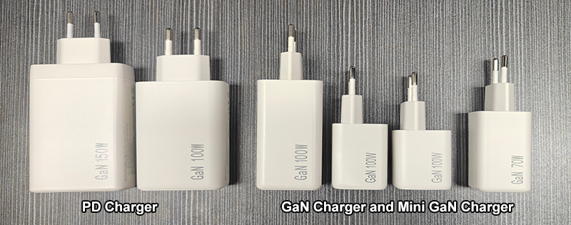
A 65W, 100W or 140W charger may need to deliver substantially more power without becoming too large. The housing therefore has to balance internal space, thermal performance, mechanical strength and appearance.
A mold is what turns that engineered housing design into a repeatable physical component.
2. When Should a Brand Develop a Custom Charger Mold?
Not all charger projects require new molds; this is one of the first decisions OEM buyers need to make.
If the client only requires customization of an existing charger (new logo, new color, minor aesthetic changes, or new packaging); then an existing housing may be sufficient.
This is generally closer to an ODM charger manufacturing project.
A dedicated mold becomes more attractive when the customer needs:
• Exclusive charger housing (thickness, custom surface texture)
• Unique dimensions
• Custom port arrangement
• New plug structure (or Foldable plug integration)
• New display opening
• Custom cable exit
• Proprietary component structure
• Product differentiation for a major retail program
For example, a brand developing a new 65W USB-C charger may want the product to be thinner than conventional 65W chargers.
That can affect almost everything inside the charger.
The PCB requires modification, the transformer needs to be relocated, the internal insulation structure requires redesign, and the position of the USB-C port needs adjustment.
And the housing mold has to follow the final engineering solution.
This is why mold development should not start too early. First, the internal structural design of the charger must be sufficiently stable.
3. Charger Mold Development Starts With Industrial Design
Before engineers design the mold itself, the product usually begins with industrial design.
This is the stage where the team decides what the charger should look and feel like.
Typical design questions include:
How large should the charger be?
Should the edges be rounded or pointed?
Where should the USB-C ports sit?
Should the charger use a foldable plug?
How thick should the housing be?
Where should the brand logo appear?
Should the surface be glossy or matte?
Should the housing have a two-tone design?
Where should the housing seam be located?
For consumer-facing products, these details matter more than many buyers initially expect.
Given the charger's compact size, even subtle design discrepancies stand out prominently.
Poorly placed casing seams can make an otherwise high-end charger look cheap.
An oversized brand logo can make the product resemble a promotional giveaway rather than a piece of technology.
Poor placement of the USB-C port can make a multi-port charger inconvenient to use.
Therefore, excellent industrial design requires taking manufacturing processes into account from the very beginning.
4. The 3D Housing Design Comes Before the Mold
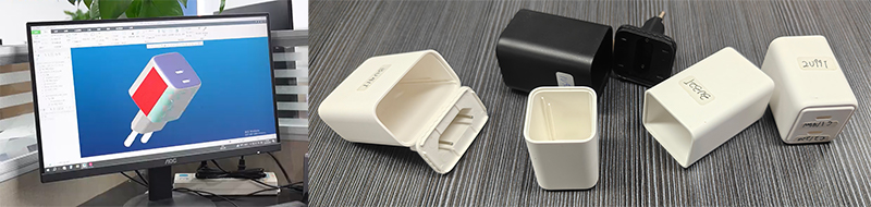
Once the industrial design direction is approved, engineers normally create a detailed 3D model.
This model preliminarily defines the physical structure of the new charger housing. Examples include: overall dimensions (length × width × height); housing wall thickness; internal reinforcing ribs; internal PCB supports/dimensions; thermal management features; housing seams; USB port locations; etc.
At this stage, the housing must be checked against the actual charger electronics. This is where electrical and mechanical engineering need to work together.
For example, imagine a 100W GaN charger designed to be extremely compact.
The industrial designer may create a beautiful slim housing. But if the PCB is 2 mm too large, the transformer touches the housing, or the required insulation distance cannot be maintained, the design cannot move directly into tooling.
This is why a professional charger manufacturer does not treat the mold as an isolated manufacturing step.
5. DFM: The Most Important Step Before Tooling
One of the most important terms in custom mold development is DFM — Design for Manufacturing.
DFM is essentially a reality check.
The question is simple: Can this design actually be manufactured reliably and economically?
Before the mold is built, engineers review the housing design for potential manufacturing problems.
DFM checks include:
Wall Thickness
Plastic walls need appropriate thickness.
If the wall is too thick, cooling may become uneven.
If it is too thin, the housing may become weak or difficult to mold.
Draft Angle
The molded part needs to release from the mold.
Without sufficient draft, the plastic housing can stick to the mold during ejection.
That can cause scratches, deformation or production problems.
Parting Line
The mold must open at some point, and the line where the two halves of the mold meet is called the parting line.
For a premium charger, engineers try to position it where it is less visible.
Ribs and Bosses
Internal ribs provide structural support. Screw bosses allow the housing or internal components to be secured.
But excessive ribs or poorly designed bosses can create molding problems or interfere with the PCB.
Sink Marks
Thicker areas of plastic can cool differently from thinner areas.
This may create visible depressions called sink marks.
For a small premium charger housing, these defects can be very noticeable.
Ejection
Engineers must also determine how the finished plastic component will be released from the mold.
Poor ejection design can damage the surface or deform small structures.
This DFM stage is where experienced engineers can save a project considerable time and money. It is much cheaper to change a CAD file than to modify a finished steel mold.
6. Choosing the Right Housing Material
The mold design also depends on the plastic material. Charger housings commonly use engineering plastics selected for mechanical strength, thermal behavior and flame resistance.
For charger applications, material selection need to consider: Flame resistance, Heat resistance, Mechanical strength, Impact resistance, Surface finish, Dimensional stability, Electrical insulation, Regulatory requirements.
For many charger projects, flame-retardant PC or PC-based materials are considered because the housing must provide both mechanical protection and electrical insulation. But material selection should not be made simply because one material is popular.
The final choice depends on the charger design, target certification, operating temperature, appearance requirements and manufacturing process (Cost is also an important factor).
For example, a compact 140W charger has very different thermal requirements from a simple 20W wall charger.
That difference can influence both material selection and housing design.
7. How the Mold Itself Is Designed
Once the housing design passes DFM review, tooling engineers can begin developing the actual mold.(Manufacturers typically seek out reliable, high-quality mold makers to source charger housings.)
The mold is usually made from precision-machined metal components.
A injection mold includes structures such as: Mold cavity, Mold core, Parting surface, Runner system, Gates, Cooling channels, Ejector system, Guide pins, Inserts etc.
The exact configuration depends on the charger housing design and expected production volume.
For simple, small hopper housings, the mold structure may be relatively straightforward; however, for more complex hopper housings, the mold might require additional slides, inserts, or moving mechanisms.
This is particularly true when the housing contains: Side openings, Undercuts, Foldable plug structures, Display windows, Complex internal clips, Special locking mechanisms.
Every additional mechanical feature can increase tooling complexity.
That does not automatically mean it is a bad design. It simply means the engineering team needs to understand the trade-off before committing to the mold.
8. Mold Flow and Plastic Filling (Extended Knowledge)
Another important consideration is how molten plastic moves through the mold.
When plastic is injected into the mold cavity, it must fill the entire shell uniformly. If the flow design is poor, manufacturers may encounter issues such as short shots, weld lines, air pockets, uneven filling, warpage, surface defects, and dimensional instability.
For more complex charger housings, engineers may use mold-flow analysis to predict how plastic will fill and cool.
This can help identify potential issues before the mold is physically manufactured.
9. Mold Manufacturing: Turning the Design Into Tooling
After the mold design is approved, the physical tooling is manufactured. Precision machining equipment is used to create the cavity, core and other mold components.
The charger housing will require features such as a high-gloss finish, fine matte texture, sandblasted texture, molded-in texture, a polished area for the logo, and spray coating, among others, to achieve the charger's intended visual design.
Surface texture can influence not only appearance but also how easily the part releases from the mold.
For an OEM charger project, the tooling team should therefore work from the approved industrial design rather than making appearance decisions independently.
10. The First Mold Trial: T0
Once the mold is completed, it is not immediately ready for mass production.
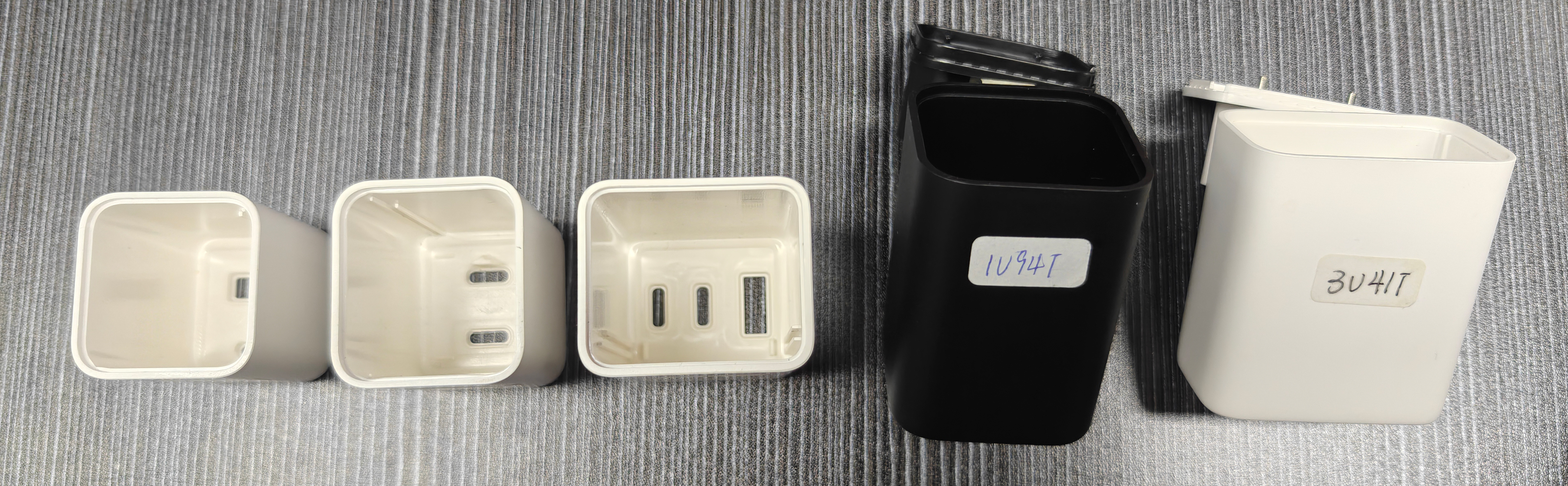
The initial mold trial is typically referred to as T0; its purpose is to verify the functionality of the basic mold.
Engineers and quality inspectors examine the initial molded parts, checking for aspects such as overall dimensions, surface appearance, flash, short shots, sink marks, warpage, ejection issues, parting line quality, hole and opening dimensions, and the finish of spray painting, metallic paint, or surface texturing.
At this stage, the goal is not perfection; rather, it is to identify areas requiring improvement.
Sometimes, the first sample looks unexpectedly good, yet it may also reveal certain issues.
Both scenarios are normal; professional mold manufacturing typically requires multiple rounds of feedback and adjustment.
11. T1, T2 and Mold Optimization
After the T0 trial, engineers make corrections where necessary.
The next trial may be called T1. Further modifications may lead to T2 or additional rounds.
This is why the phrase “mold development” is more accurate than simply “mold making.”
The project is not finished when the steel is machined.
The real goal is to create a mold that can consistently produce good parts.
12. Why Charger Housing and PCB Must Be Validated Together
One common mistake in custom charger projects is validating the plastic housing separately from the electronics. That can create problems later.
The final charger is an assembled system.
The PCB must fit inside the housing.
The USB-C port must align with the opening.
The transformer requires sufficient clearance.
Space is needed for insulation materials.
The AC power plug must be installed correctly.
Heat-dissipating components must not interfere with the housing.
The assembly line must also be able to install all components efficiently.
For example, a housing may pass dimensional inspection but still be difficult to assemble because the PCB cannot slide into position easily. That is a manufacturing problem, not simply a cosmetic problem.
For this reason, charger factories with both electrical and mechanical engineering capability can have a significant advantage during custom development.
13. Thermal Design Can Affect the Mold
This point is particularly important for high-power chargers. A charger housing is part of the thermal system.
It cannot solve every thermal problem by itself, but its structure influences how heat moves away from internal components.
This becomes increasingly important as charger power increases.
A 20W charger has relatively modest thermal requirements.
A 65W GaN charger is more demanding.
A 100W or 140W charger requires even more careful thermal engineering.
Engineers need to consider: internal air volume, PCB placement, the gap between components and the enclosure, thermal pads, heat dissipation structures, enclosure materials, and external surface area.
This is one reason a custom charger mold should not be designed purely from an industrial-design perspective.
The housing must work with the electrical and thermal architecture.
ZONSAN's existing charger manufacturing work covers products from lower-power wall chargers through high-power GaN and PD charging solutions, and its current OEM/ODM projects include private mold cooperation.
14. Custom Mold vs Existing Mold: Which Is Better?
There is no one-size-fits-all answer; it depends on specific business objectives.
| Requirement | Existing Mold | Custom Mold |
| Launch speed | Faster | Slower |
| Initial tooling cost | Lower | Higher |
| Housing uniqueness | Limited | High |
| Brand differentiation | Moderate | Strong |
| MOQ flexibility | Usually easier | Depends on tooling |
| Engineering work | Lower | Higher |
| Product exclusivity | Limited | High |
| Long-term product platform | Good | Excellent |
| Best for | ODM / quick launch | OEM / exclusive product |
For a small e-commerce brand testing a new product category, using an existing charger platform may make more sense.
For a telecom operator, retailer, established electronics brand or large distributor launching a proprietary charger, a dedicated mold may provide a better long-term return.
The right decision is not “custom is better.”
The right question is: Does the expected production volume and product differentiation justify the tooling investment?
15. How Mold Cost Is Determined
Many buyers ask one simple question: How much does a charger mold cost?
There is no universal pricing standard; mold costs depend on the design (Housing structure, dimensions, material, surface finish, etc.).
A simple housing with two relatively straightforward shells is very different from a multi-piece housing with a foldable plug, display opening and complex internal clips.
Tooling should therefore be evaluated as part of the entire project rather than as an isolated quotation.
A cheap mold that requires frequent maintenance or produces unstable parts can become more expensive over time.
16. How Long Does Charger Mold Development Take?
The development schedule depends heavily on design complexity and how quickly engineering decisions are approved.
A typical project include: Industrial design → 3D mechanical design → DFM → mold design → tooling → T0 → modification → T1/T2 → assembly validation → pilot production
The timeline can be affected by:
How complete the initial design is
• Whether the PCB is already finalized
• Whether the housing is new
• Whether plug structures are customized
• Number of mold components
• Number of trial rounds
• Certification requirements
• Customer approval speed
For this reason, buyers should be cautious about factories promising an extremely short tooling cycle without explaining what is actually included.
Fast development is valuable. But fast development without proper validation can create problems during mass production.
* custom charger development timeline↗
17. What Happens After the Mold Is Approved?
Once the housing samples are approved, the project moves toward pilot production.
The engineering team normally verifies: Housing dimensions, PCB fit, Port alignment, Plug installation, Assembly sequence, Surface appearance, Mechanical strength, Thermal behavior, Electrical safety, Final product dimensions.
The pilot run is particularly important. A mold may produce ten excellent samples but still reveal problems when hundreds or thousands of units are manufactured continuously.
Mass production introduces another variable: consistency.
The mold needs to produce stable parts repeatedly. Injection temperature, pressure, cooling time, material drying and machine settings all need to be controlled.
That is why tooling validation and manufacturing process control should be considered together.
18. How Charger Factories Use Mold Development for OEM Projects
For OEM customers, a charger mold is often part of a larger product-development project.
The customer may start with a basic requirement: “We need a 65W type c charger that looks different from the current products in our market.”
That single sentence can lead to a long engineering discussion. (If the factory's existing chargers do not meet the buyer's appearance requirements)
The factory sale will clarify the following details with the buyer: target market, plug standard, number of ports, maximum output power, PD/PPS requirements, GaN or silicon architecture, target dimensions, logo placement, housing material, surface finish, packaging, and certifications.
Only after these requirements are clear can the mechanical design and mold strategy be finalized.
This is why an experienced OEM charger manufacturer can contribute much more than simply producing plastic parts. The factory can help identify whether the proposed housing is actually compatible with the charging architecture.
19. Mold Development for 20W, 65W, 100W and 140W Chargers
Power rating does not automatically determine mold complexity. However, higher-power chargers often create more demanding mechanical constraints.
20W Charger
A 20W charger can usually use a relatively compact housing.
The main priorities are often: Small size, Good appearance, Port alignment, Plug structure, Cost efficiency.
45W Charger
At 45W, thermal and internal-space considerations become more important. The housing may need to accommodate a larger power architecture while maintaining a compact form.
65W Charger
The 65W category is particularly interesting for OEM brands because it can serve phones, tablets and many laptops.
A custom 65W charger housing may need to balance: Compact size, Thermal performance, USB C port location and number, GaN architecture, connector design, Mechanical strength.
100W Charger
At 100W, internal thermal management becomes even more important. The housing design must work closely with the PCB and component layout.
140W Charger
For a 140W PD3.1 charger, the mechanical design becomes even more demanding. High power, thermal management, port structure and certification requirements all need to be considered together.
ZONSAN currently offers OEM/ODM charger platforms across multiple power levels, including 65W, 100W and 140W-class solutions, with private mold cooperation available for customized projects.
20. Common Charger Mold Problems
A good mold development process is also about preventing problems.
Some common issues include:
Flash — Excess plastic appears along the mold parting line.
Warping — The molded housing changes shape during cooling.
Sink Marks — Depressions appear around thicker sections.
Short Shot — The plastic does not completely fill the cavity.
Weld Lines — Visible lines form where two plastic flow fronts meet.
Poor Surface Finish — The final texture does not match the approved sample.
Dimensional Variation — The housing dimensions change beyond acceptable tolerance.
Assembly Interference — The housing looks correct but does not fit the PCB or internal components correctly.
Difficult Ejection — The part sticks to the mold or becomes damaged during ejection.
Most of these problems are easier and cheaper to solve before the mold is finalized.
21. What Should Buyers Ask a Charger Factory Before Approving a Mold?
If you are sourcing a custom charger, do not ask only: “How much is the mold?”
Ask more useful questions.
Engineering
Who owns the mechanical design?
Can the factory perform DFM?
Can the housing be designed around our PCB?
Can the factory support mechanical revisions?
Tooling
Where will the mold be manufactured?
What mold material will be used?
What is the expected tooling life?
Are mold modifications included?
Sampling
How many trial rounds are included?
What is the T0/T1/T2 process?
How are samples approved?
What happens if the housing fails assembly testing?
Production
Can the same factory handle mass production?
Is the injection molding process controlled internally?
How is dimensional consistency monitored?
What happens when the mold requires maintenance?
Product Development
Can electrical and mechanical engineers work together?
Can the factory support PD/PPS/GaN charger development?
Can the factory help with certification?
Can the factory support multiple power levels?
These questions tell you much more about a manufacturer's actual engineering capability than a low tooling quotation.
22. Why Mold Development Is More Than a Cosmetic Process
It is easy to view a charger housing merely as a plastic shell, but that is far from the case.
With modern GaN chargers, as power density increases, every single millimeter inside the housing becomes critical.
A few millimeters of excess plastic or a misplaced internal rib can compromise the structural integrity of the entire product.
Therefore, the development of the charger mold should be part of the engineering discussions from the very beginning.
23. How ZONSAN Supports Custom Charger Mold Development
For an OEM or ODM charger buyer, the real value of a manufacturer is not simply access to a mold shop. It is the ability to connect the entire product-development chain.
ZONSAN has specialized in charger manufacturing since 2009 and currently provides OEM/ODM development for USB-C, PD, PPS and GaN charging products across multiple power ranges. Its current manufacturing information highlights an independent R&D engineering team, automated production equipment, charger testing capabilities and private mold cooperation for customized projects.
That matters because a custom housing cannot be developed independently from the charger itself.
For a new project, the engineering process may connect: Industrial Design → Mechanical Design → DFM → PCB Development → Mold Development → Prototype → DVT/PVT → Certification → Mass Production
This integrated approach can reduce unnecessary redesign between the mechanical and electrical teams.
For buyers developing a new 30W, 65W, 100W or 140W charger, that can be much more valuable than simply finding the lowest tooling quotation.
24. Existing Mold or Private Mold? A Practical Decision
Here is a simple way to think about it.
Choose an existing mold / ODM platform when:
• You need a fast launch.
• The housing does not need to be unique.
• Your main differentiation is packaging or branding.
• Initial order volume is uncertain.
• You want to reduce development cost.
Consider a private mold / OEM project when:
• Housing appearance is part of your brand.
• You need exclusive dimensions.
• Competitors already use similar charger housings.
Y• ou expect repeat orders.
• You are building a long-term product line.
• You need a specific port or plug structure.
• You want control over future product revisions.
For many established B2B brands, the best strategy is actually a combination.
Start with an existing platform to test demand. Then develop a private housing when the product reaches a predictable volume.
That reduces risk while still creating a path toward product differentiation.
Final Thoughts
A charger mold may look like a simple piece of metal from the outside. In reality, it is the physical result of many engineering decisions.
The mold has to work with the industrial design.
The industrial design has to work with the PCB.
The PCB has to fit the thermal architecture.
The housing has to survive assembly.
And the entire system has to remain consistent when production moves from a few prototypes to thousands of units.
That is why good charger mold development starts long before the mold is machined.
For brands looking for an OEM charger manufacturer, the better question is not simply: “Can you make a custom mold?”
A better question is: “Can your engineering team take my charger from industrial design through tooling, validation and stable mass production?”
That difference matters.
A factory that can connect mechanical engineering, electrical engineering, tooling, testing and production is in a much stronger position to deliver a reliable custom charger. And for today's 45W, 65W, 100W, 140W and higher-power GaN chargers, that integrated engineering approach is becoming increasingly important.
FAQ: Charger Mold Development
Q1: What is charger mold development?
Charger mold development is the process of designing and manufacturing a dedicated mold for producing a charger's plastic housing or other molded components. It normally includes DFM, mold design, tooling, trial molding, sample validation and mass-production approval.
Q2: Does every custom charger need a new mold?
No. If an existing housing meets the customer's requirements, an ODM solution can avoid new tooling. A private mold is more suitable when the customer needs an exclusive housing, dimensions, port layout or mechanical structure.
Q3: How long does charger mold development take?
The timeline depends on housing complexity, design readiness, tooling structure and the number of trial modifications. The full process may include industrial design, DFM, tooling, T0/T1/T2 trials, assembly validation and pilot production.
Q4: What is DFM in charger mold development?
DFM means Design for Manufacturing. Engineers review the charger housing before tooling to identify problems involving wall thickness, draft angles, parting lines, ribs, ejection, plastic flow and assembly.
Q5: What are T0, T1 and T2 mold trials?
They are different stages of mold sampling. T0 is typically the first trial used to identify basic tooling issues. T1 and T2 trials are subsequent rounds after engineering modifications and optimization.
Q6: Can a charger factory customize the housing around an existing PCB?
Yes, depending on the manufacturer's engineering capabilities. A professional charger manufacturer can develop the mechanical housing around PCB dimensions, USB ports, transformer placement, insulation requirements and thermal constraints.
Q7: Is a custom mold worth it for a 65W charger?
It can be, especially when a brand needs an exclusive housing or long-term product differentiation. For smaller or uncertain orders, an existing ODM platform may provide a lower-risk starting point.
Q8: Can a 100W or 140W GaN charger use a custom mold?
Yes. In fact, high-power GaN chargers can benefit from careful mechanical engineering because thermal management, component clearance and internal space become increasingly important as power density rises.
Q9: What plastic is commonly used for charger housings?
Engineering plastics such as PC and PC-based flame-retardant materials are commonly considered for charger housings. The final material should be selected according to thermal, mechanical, electrical, appearance and compliance requirements.
Q10: What should I provide to a charger manufacturer for mold development?
Useful information includes target wattage, dimensions, port configuration, plug type, industrial design references, target market, certification requirements, expected order volume, branding requirements and any existing PCB or mechanical drawings.
Q11: Can the same charger factory develop the mold and manufacture the charger?
Yes. This can be an advantage because the same engineering team can connect tooling development with PCB assembly, housing assembly, testing and mass production.
Q12: What is the difference between OEM and ODM charger mold development?
With ODM, the factory usually starts from an existing charger platform or housing and offers limited customization. With OEM or fully customized development, the customer may require a dedicated housing, private mold, customized PCB or other proprietary specifications.
Reviewers by: Zonsan Team and Engineers – Lucas and Miller
Last Review Date: [September 03, 2026]
For a telecom operator, retailer, established electronics brand or large distributor launching a proprietary charger, a dedicated mold may provide a better long-term return.
The right decision is not “custom is better.”
The right question is: Does the expected production volume and product differentiation justify the tooling investment?
15. How Mold Cost Is Determined
Many buyers ask one simple question: How much does a charger mold cost?
There is no universal pricing standard; mold costs depend on the design (Housing structure, dimensions, material, surface finish, etc.).
A simple housing with two relatively straightforward shells is very different from a multi-piece housing with a foldable plug, display opening and complex internal clips.
Tooling should therefore be evaluated as part of the entire project rather than as an isolated quotation.
A cheap mold that requires frequent maintenance or produces unstable parts can become more expensive over time.
16. How Long Does Charger Mold Development Take?
The development schedule depends heavily on design complexity and how quickly engineering decisions are approved.
A typical project include: Industrial design → 3D mechanical design → DFM → mold design → tooling → T0 → modification → T1/T2 → assembly validation → pilot production
The timeline can be affected by:
How complete the initial design is
• Whether the PCB is already finalized
• Whether the housing is new
• Whether plug structures are customized
• Number of mold components
• Number of trial rounds
• Certification requirements
• Customer approval speed
For this reason, buyers should be cautious about factories promising an extremely short tooling cycle without explaining what is actually included.
Fast development is valuable. But fast development without proper validation can create problems during mass production.
* custom charger development timeline↗
17. What Happens After the Mold Is Approved?
Once the housing samples are approved, the project moves toward pilot production.
The engineering team normally verifies: Housing dimensions, PCB fit, Port alignment, Plug installation, Assembly sequence, Surface appearance, Mechanical strength, Thermal behavior, Electrical safety, Final product dimensions.
The pilot run is particularly important. A mold may produce ten excellent samples but still reveal problems when hundreds or thousands of units are manufactured continuously.
Mass production introduces another variable: consistency.
The mold needs to produce stable parts repeatedly. Injection temperature, pressure, cooling time, material drying and machine settings all need to be controlled.
That is why tooling validation and manufacturing process control should be considered together.
18. How Charger Factories Use Mold Development for OEM Projects
For OEM customers, a charger mold is often part of a larger product-development project.
The customer may start with a basic requirement: “We need a 65W type c charger that looks different from the current products in our market.”
That single sentence can lead to a long engineering discussion. (If the factory's existing chargers do not meet the buyer's appearance requirements)
The factory sale will clarify the following details with the buyer: target market, plug standard, number of ports, maximum output power, PD/PPS requirements, GaN or silicon architecture, target dimensions, logo placement, housing material, surface finish, packaging, and certifications.
Only after these requirements are clear can the mechanical design and mold strategy be finalized.
This is why an experienced OEM charger manufacturer can contribute much more than simply producing plastic parts. The factory can help identify whether the proposed housing is actually compatible with the charging architecture.
19. Mold Development for 20W, 65W, 100W and 140W Chargers
Power rating does not automatically determine mold complexity. However, higher-power chargers often create more demanding mechanical constraints.
20W Charger
A 20W charger can usually use a relatively compact housing.
The main priorities are often: Small size, Good appearance, Port alignment, Plug structure, Cost efficiency.
45W Charger
At 45W, thermal and internal-space considerations become more important. The housing may need to accommodate a larger power architecture while maintaining a compact form.
65W Charger
The 65W category is particularly interesting for OEM brands because it can serve phones, tablets and many laptops.
A custom 65W charger housing may need to balance: Compact size, Thermal performance, USB C port location and number, GaN architecture, connector design, Mechanical strength.
100W Charger
At 100W, internal thermal management becomes even more important. The housing design must work closely with the PCB and component layout.
140W Charger
For a 140W PD3.1 charger, the mechanical design becomes even more demanding. High power, thermal management, port structure and certification requirements all need to be considered together.
ZONSAN currently offers OEM/ODM charger platforms across multiple power levels, including 65W, 100W and 140W-class solutions, with private mold cooperation available for customized projects.
20. Common Charger Mold Problems
A good mold development process is also about preventing problems.
Some common issues include:
Flash — Excess plastic appears along the mold parting line.
Warping — The molded housing changes shape during cooling.
Sink Marks — Depressions appear around thicker sections.
Short Shot — The plastic does not completely fill the cavity.
Weld Lines — Visible lines form where two plastic flow fronts meet.
Poor Surface Finish — The final texture does not match the approved sample.
Dimensional Variation — The housing dimensions change beyond acceptable tolerance.
Assembly Interference — The housing looks correct but does not fit the PCB or internal components correctly.
Difficult Ejection — The part sticks to the mold or becomes damaged during ejection.
Most of these problems are easier and cheaper to solve before the mold is finalized.
21. What Should Buyers Ask a Charger Factory Before Approving a Mold?
If you are sourcing a custom charger, do not ask only: “How much is the mold?”
Ask more useful questions.
Engineering
Who owns the mechanical design?
Can the factory perform DFM?
Can the housing be designed around our PCB?
Can the factory support mechanical revisions?
Tooling
Where will the mold be manufactured?
What mold material will be used?
What is the expected tooling life?
Are mold modifications included?
Sampling
How many trial rounds are included?
What is the T0/T1/T2 process?
How are samples approved?
What happens if the housing fails assembly testing?
Production
Can the same factory handle mass production?
Is the injection molding process controlled internally?
How is dimensional consistency monitored?
What happens when the mold requires maintenance?
Product Development
Can electrical and mechanical engineers work together?
Can the factory support PD/PPS/GaN charger development?
Can the factory help with certification?
Can the factory support multiple power levels?
These questions tell you much more about a manufacturer's actual engineering capability than a low tooling quotation.
22. Why Mold Development Is More Than a Cosmetic Process
It is easy to view a charger housing merely as a plastic shell, but that is far from the case.
With modern GaN chargers, as power density increases, every single millimeter inside the housing becomes critical.
A few millimeters of excess plastic or a misplaced internal rib can compromise the structural integrity of the entire product.
Therefore, the development of the charger mold should be part of the engineering discussions from the very beginning.

23. How ZONSAN Supports Custom Charger Mold Development
For an OEM or ODM charger buyer, the real value of a manufacturer is not simply access to a mold shop. It is the ability to connect the entire product-development chain.
ZONSAN has specialized in charger manufacturing since 2009 and currently provides OEM/ODM development for USB-C, PD, PPS and GaN charging products across multiple power ranges. Its current manufacturing information highlights an independent R&D engineering team, automated production equipment, charger testing capabilities and private mold cooperation for customized projects.
That matters because a custom housing cannot be developed independently from the charger itself.
For a new project, the engineering process may connect: Industrial Design → Mechanical Design → DFM → PCB Development → Mold Development → Prototype → DVT/PVT → Certification → Mass Production
This integrated approach can reduce unnecessary redesign between the mechanical and electrical teams.
For buyers developing a new 30W, 65W, 100W or 140W charger, that can be much more valuable than simply finding the lowest tooling quotation.
24. Existing Mold or Private Mold? A Practical Decision
Here is a simple way to think about it.
Choose an existing mold / ODM platform when:
• You need a fast launch.
• The housing does not need to be unique.
• Your main differentiation is packaging or branding.
• Initial order volume is uncertain.
• You want to reduce development cost.
Consider a private mold / OEM project when:
• Housing appearance is part of your brand.
• You need exclusive dimensions.
• Competitors already use similar charger housings.
Y• ou expect repeat orders.
• You are building a long-term product line.
• You need a specific port or plug structure.
• You want control over future product revisions.
For many established B2B brands, the best strategy is actually a combination.
Start with an existing platform to test demand. Then develop a private housing when the product reaches a predictable volume.
That reduces risk while still creating a path toward product differentiation.
Final Thoughts
A charger mold may look like a simple piece of metal from the outside. In reality, it is the physical result of many engineering decisions.
The mold has to work with the industrial design.
The industrial design has to work with the PCB.
The PCB has to fit the thermal architecture.
The housing has to survive assembly.
And the entire system has to remain consistent when production moves from a few prototypes to thousands of units.
That is why good charger mold development starts long before the mold is machined.
For brands looking for an OEM charger manufacturer, the better question is not simply: “Can you make a custom mold?”
A better question is: “Can your engineering team take my charger from industrial design through tooling, validation and stable mass production?”
That difference matters.
A factory that can connect mechanical engineering, electrical engineering, tooling, testing and production is in a much stronger position to deliver a reliable custom charger. And for today's 45W, 65W, 100W, 140W and higher-power GaN chargers, that integrated engineering approach is becoming increasingly important.
FAQ: Charger Mold Development
Q1: What is charger mold development?
Charger mold development is the process of designing and manufacturing a dedicated mold for producing a charger's plastic housing or other molded components. It normally includes DFM, mold design, tooling, trial molding, sample validation and mass-production approval.
Q2: Does every custom charger need a new mold?
No. If an existing housing meets the customer's requirements, an ODM solution can avoid new tooling. A private mold is more suitable when the customer needs an exclusive housing, dimensions, port layout or mechanical structure.
Q3: How long does charger mold development take?
The timeline depends on housing complexity, design readiness, tooling structure and the number of trial modifications. The full process may include industrial design, DFM, tooling, T0/T1/T2 trials, assembly validation and pilot production.
Q4: What is DFM in charger mold development?
DFM means Design for Manufacturing. Engineers review the charger housing before tooling to identify problems involving wall thickness, draft angles, parting lines, ribs, ejection, plastic flow and assembly.
Q5: What are T0, T1 and T2 mold trials?
They are different stages of mold sampling. T0 is typically the first trial used to identify basic tooling issues. T1 and T2 trials are subsequent rounds after engineering modifications and optimization.
Q6: Can a charger factory customize the housing around an existing PCB?
Yes, depending on the manufacturer's engineering capabilities. A professional charger manufacturer can develop the mechanical housing around PCB dimensions, USB ports, transformer placement, insulation requirements and thermal constraints.
Q7: Is a custom mold worth it for a 65W charger?
It can be, especially when a brand needs an exclusive housing or long-term product differentiation. For smaller or uncertain orders, an existing ODM platform may provide a lower-risk starting point.
Q8: Can a 100W or 140W GaN charger use a custom mold?
Yes. In fact, high-power GaN chargers can benefit from careful mechanical engineering because thermal management, component clearance and internal space become increasingly important as power density rises.
Q9: What plastic is commonly used for charger housings?
Engineering plastics such as PC and PC-based flame-retardant materials are commonly considered for charger housings. The final material should be selected according to thermal, mechanical, electrical, appearance and compliance requirements.
Q10: What should I provide to a charger manufacturer for mold development?
Useful information includes target wattage, dimensions, port configuration, plug type, industrial design references, target market, certification requirements, expected order volume, branding requirements and any existing PCB or mechanical drawings.
Q11: Can the same charger factory develop the mold and manufacture the charger?
Yes. This can be an advantage because the same engineering team can connect tooling development with PCB assembly, housing assembly, testing and mass production.
Q12: What is the difference between OEM and ODM charger mold development?
With ODM, the factory usually starts from an existing charger platform or housing and offers limited customization. With OEM or fully customized development, the customer may require a dedicated housing, private mold, customized PCB or other proprietary specifications.
Reviewers by: Zonsan Team and Engineers – Lucas and Miller
Last Review Date: [September 03, 2026]